


 587 / 1278

Modell- und Maßänderungen vorbehalten.
Unsere AGBs finden Sie auf
www.camozzi.de.
2
Wegeventile Serie 7
ANSTEUERN >
KATALOG
>
Version 8.8
/2.25.02
2
ANSTEUERN
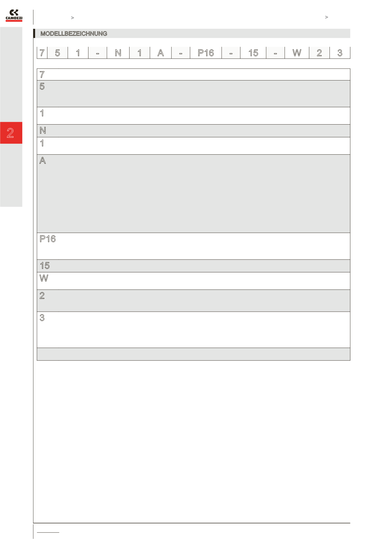
7
SERIE
5
WEGE / FUNKTION
5 = 5/2
6 = 5/3 Mitte geschlossen
7 = 5/3 Mitte offen
8 = 5/3 Mitte belüftet
1
BAUBREITE
1 = 26 mm
2 = 18 mm
N
GRUNDPLATTEN
N = (Reihengrundplatten, Abgänge stirnseitig)
1
ANSCHLÜSSSE
1 = G1/4” (26 mm)
2 = G1/8” (18 mm)
A
ANZAHL VENTILE
A = 1 *
B = 2 *
C = 3 *
D = 4 *
E = 5 *
F = 6 *
G = 7 *
H = 8 *
K = 9 *
L = 10 *
M = 11 *
N = 12 *
P = 13 *
R = 14 *
S = 15 *
P16
BETÄTIGUNGSARTEN
33 = pneumatisch/bistabil
36 = pneumatisch/monostabil
P11 = elektro-pneumatisch/bistabil
P16 = elektro-pneumatisch/monostabil
15
VORSTEUERVENTIL
15 = 15x15 mm
W
WEGEVENTILE
W = Serie W
P = Serie P **
2
ANSCHLUSSART
1 = Kabel 300 mm (Serie W, nur 24 V DC) **
2 = 2 Steckerfahnen (Serie W, 24V - 48V DC)
5 = 2 Steckerfahnen+Erdung (Serie P) **
3
SPANNUNGEN
3 = 24V DC
4 = 48V DC **
6 = 110V DC (mit Magnetventil Serie P)**
B = 24V 50/60 Hz (mit Magnetventil Serie P)**
C = 48V 50/60 Hz (mit Magnetventil Serie P)**
D = 110V 50/60 Hz (mit Magnetventil Serie P)**
* komplett mit Endplatte
** auf Anfrage
MODELLBEZEICHNUNG
7 5 1 -
N 1 A -
P16 -
15 -
W 2 3