
General terms and conditions for sale are available on
www.camozzi.com.2
Series AP proportional valves
CONTROL >
C_FLUID CONTROL CATALOGUE
>
2018
113
CONTROL
CODING EXAMPLE
AP
SERIES
7
BODY:
6 = Size 16 mm
7 = Size 22 mm
2
NUMBER OF WAYS:
2 = 2-way
1
VALVE FUNCTION:
1 = NC
1
PORTS:
0 = M5 (for size 16 mm only)
1 = G1/8 (for size 22 mm only)
L = male hose adaptor (for body in PVDF only, size 16 mm)
4 = with rear flanges
5 = with lower flanges
L
NOMINAL DIAMETER:
D = ø 0.8 mm (for size 16 mm only)
F = ø 1 mm
H = ø 1.2 mm
L = ø 1.6 mm
N = ø 2 mm (for size 22 mm only)
Q = ø 2.4 mm (for size 22 mm only)
R
SEAL MATERIAL:
R = NBR
W = FKM
2
BODY MATERIAL:
2 = brass
3 = PVDF (for size 16 mm only)
U
ENCAPSULATING MATERIAL:
G = PA (for size 16 mm only)
U = PET (for size 22 mm only)
7
SOLENOID DIMENSIONS:
P = 16x26 DIN EN 175301-803-C (for size 16 mm only)
7 = 22x22 DIN 43650 B (for size 22 mm only)
11
SOLENOID VOLTAGE:
H = 12 V DC 3 W (for size 16 mm only)
7 = 24 V DC 3 W (for size 16 mm only)
11 = 24 V DC 6.5 W (for size 22 mm only)
12 = 12 V DC 6.5 W (for size 22 mm only)
OX2
VERSION:
OX2 = version with ASTM G93-03 Certification Level B
(FKM seals only)
= non-certified NBR version
AP -
7 2 1 1 -
L R 2 - U 7 11 OX2
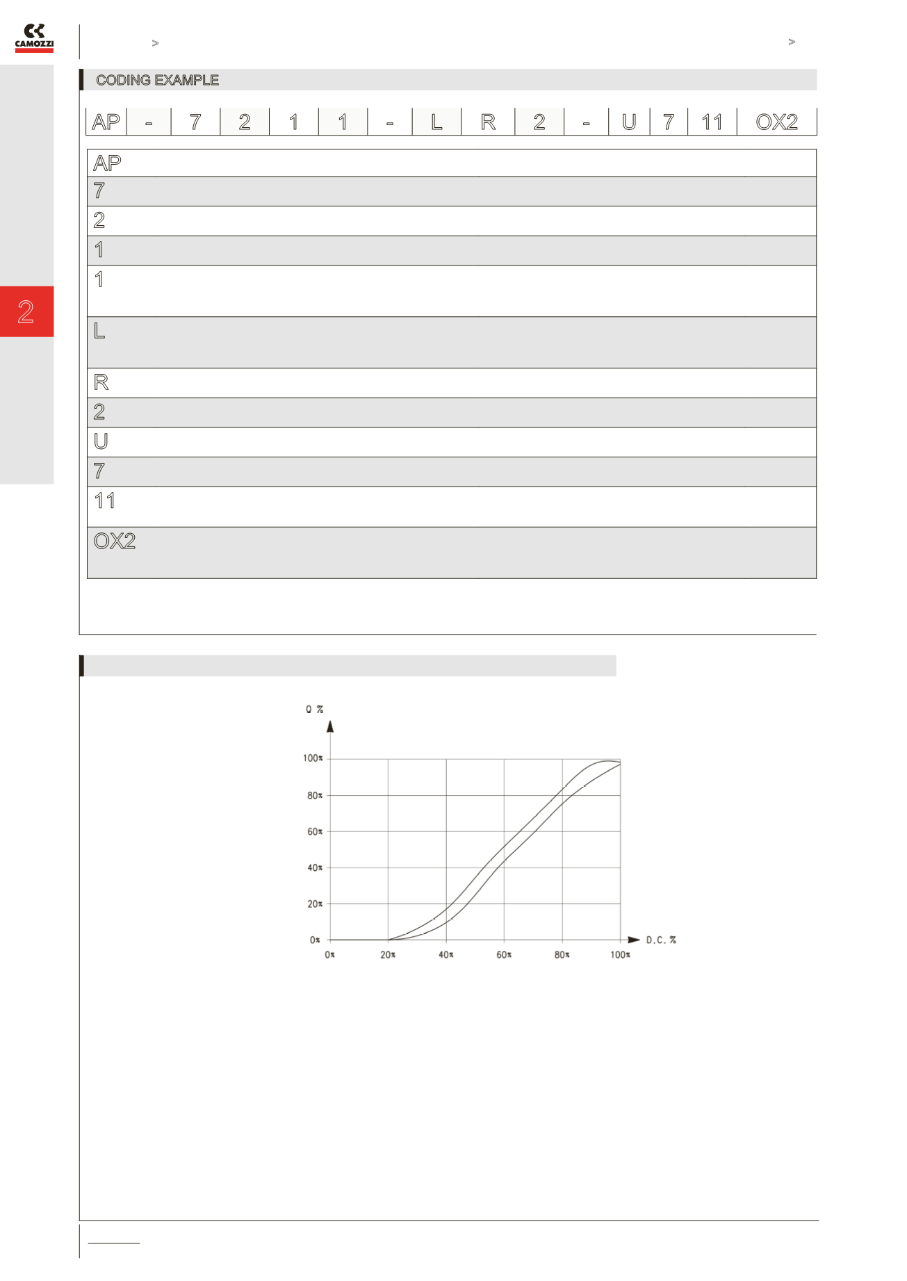
Flow characteristic curve of a
proportional valve
Q = flow
D.C. = duty cycle
FLOW GRAPH


