
General terms and conditions for sale are available on
www.camozzi.com.2
Series AP proportional valves
CONTROL >
C_FLUID CONTROL CATALOGUE
>
2018
117
CONTROL
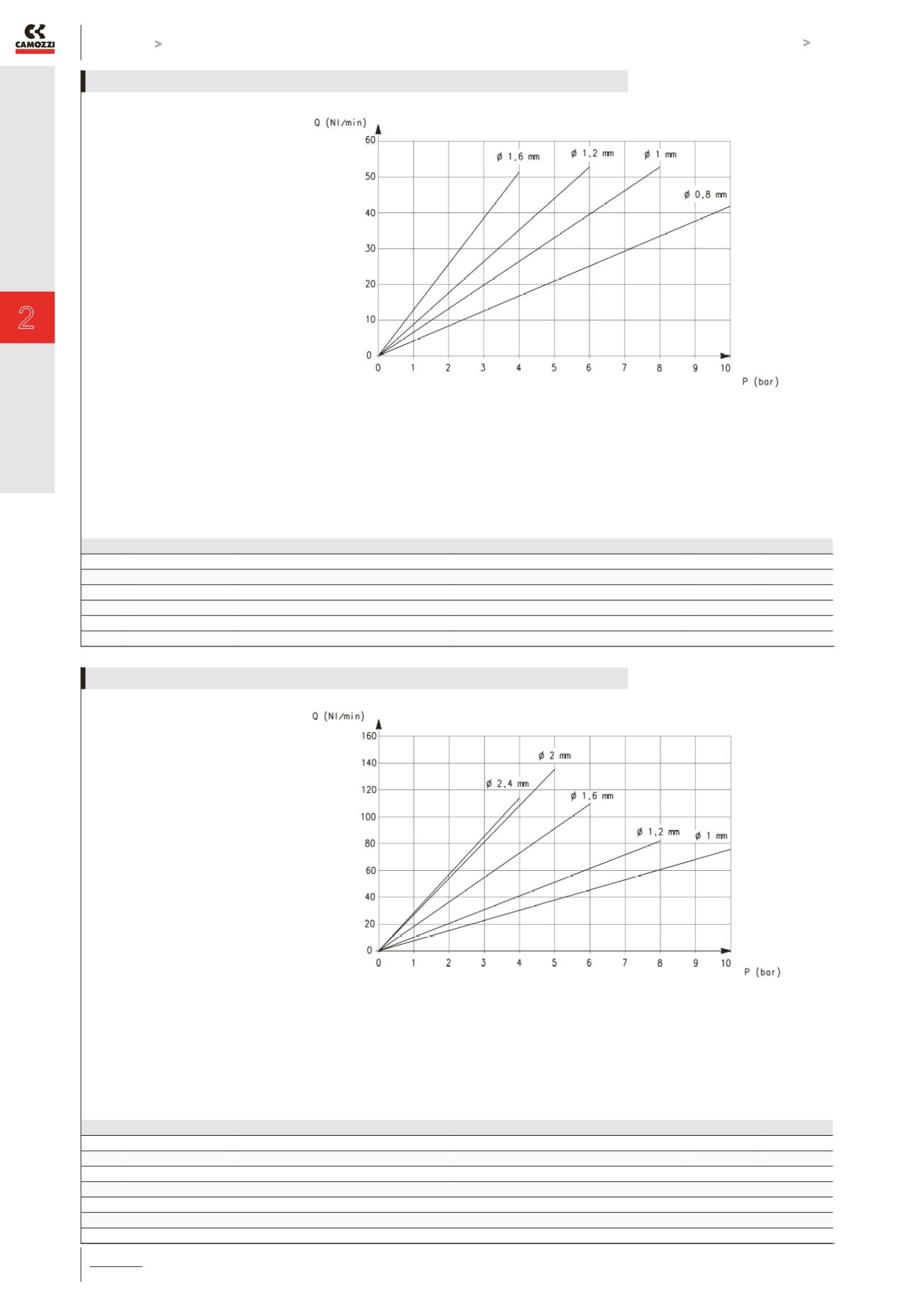
Maximum flow according to the inlet
pressure
DIAGRAM LEGEND:
Q = flow (Nl/min)
I = current (A)
RESPONSE TIMES calculated according to the maximum flow at each operating pressure. [ Electromechanical response time: 10 ms ]
ø
Pin [bar]
Load response time [ms]
Exhaust response time [ ms ]
0% - 10% 0% - 90% 10% - 90%
100% - 90% 100% - 10% 90% - 10%
0.8 mm
10
12 43 31
11 39 28
1 mm
8
12 42 30
11 38 27
1.2 mm
6
10 41 31
11 41 30
1.6 mm
4
10 40 30
11 40 29
MAXIMUM FLOW AND RESPONSE TIMES - size 16mm
Maximum flow according to the inlet
pressure
DIAGRAM LEGEND:
Q = flow (Nl/min)
I = current (A)
RESPONSE TIMES calculated according to the maximum flow at each operating pressure. [ Electromechanical response time: 10 ms ]
ø
Pin [bar]
Load response time [ms]
Exhaust response time [ ms ]
0% - 10% 0% - 90% 10% - 90%
100% - 90% 100% - 10% 90% - 10%
1 mm
10
10 36 26
10 36 26
1.2 mm
8
10 45 35
12 38 26
1.6 mm
6
12 45 33
12 40 28
2 mm
5
12 42 30
11 34 26
2.4 mm
4
11 45 34
12 44 32
MAXIMUM FLOW AND RESPONSE TIMES - size 22mm


