


 86 / 218

Required air for a pneumatic cylinder
In previous sections, we analyzed the consumption of free air, i.e. the amount of air that the compressor must
produce to constantly supply the pneumatic system, we now analyze the requirement of compressed air by a
pneumatic cylinder, i.e. the quantity of air necessary for it to complete a particular operation in the desired time.
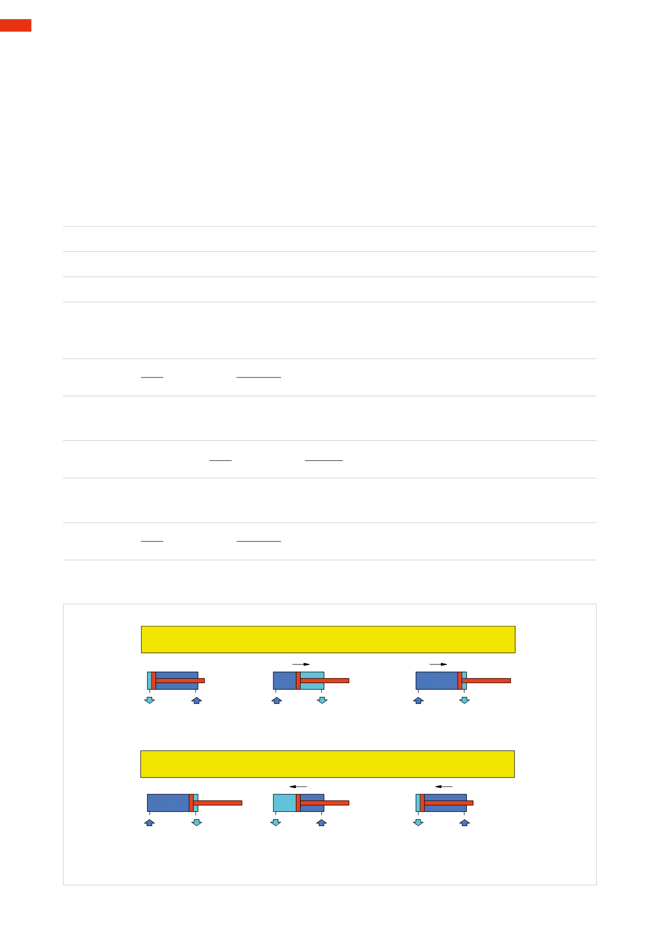
Figure 39
Example:
a cylinder with diameter
D
=50
mm
stroke
C
= 250
mm
with a pressure
p= 6 bar
should execute a positive stroke in
1.5 seconds
.
Depending on the time available we need to size the control valve and the connecting pipes, we
calculate the
consumption of compressed air during the positive stroke
.
Thrust surface of the cylinder
S
=
r
2
*
π
S
=3,14 *
25
2
S
=
1962
mm
2
Volume of the thrust chamber
V
s
=
S
*
C
V
s
=1962 *
250
V
s
=490.625mm
3
V
s
=
0,49
dm
3
Q
s
=
V
s
*
(
p
+1)
Q
s
=
0,49 *
(6+1)
Q
s
=
3,43
Nl
This quantity of air needs to be inserted in the rear cylinder chamber in a time
t
= 1.5
s
the required flow
Q
rs
towards the control valve is:
Q
rs
=
Q
s
Q
rs
=
3,43
Q
rs
=2,29
Nl
⁄
s
Q
rs
=
137
Nl
/
min
t
1,5
The average speed of the cylinder is:
V
=
C
V
=
250
V
=
167
mm
/
s
t
1,5
If we reduce the stroke time to 1 second, the request of air
Q
rs
would be:
Q
rs
=
Q
s
Q
rs
=
3,43
Q
rs
=3,43
Nl
⁄
s
Q
rs
=
206
Nl
/
min
t
1
By increasing the speed the request of air increases, therefore the control valve should be sized appropriately.
Q
rs
= (Q
s
: seconds required for thepositive stroke) x 60
t
= time required for the stroke (sec.)
Q
s
=Free air consumption for the positive strokeNl
Q
rt
= (Q
t
: secondsRequired for negative stroke) x 60
t
= time required for the stroke (sec.)
Q
t
=Free air consumption for thenegative strokeNl
Q
rs
=Request of air inNl /min. for thepositive stroke
Q
rt
= request air inNl /min. for thenegative stroke
Fig. 39
3
84
CAMOZZI
>
CYLINDERS