


 81 / 218

CYLINDERS
Figure 32
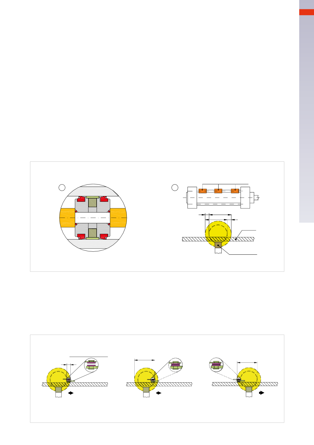
Behaviour of the switch in positive stroke.
A
: the magnetic field begins to act on the switch but the force generated is not sufficient to move the electric
contact. (hysteresis
H
).
B
: the proximity switch is located in the zone of maximum attraction of the magnetic field; the electrical contact
closes and remains closed for the length
b
.
C
: themagnetic fieldmoves away from the proximity switch but the strength is still sufficient to keep the contact
closed.
Magnetic cylinders
Inpneumaticcircuits, acylinder isusuallyequippedwithdeviceswhichdetect theendpositionof thepiston rod/piston.
These devices can be operated via the piston rod or the piston. By placing a permanent magnet in the piston, a
magnetic proximity switch is able to detect themagnetic field generated.
The orientation of the magnetic field is at its maximum only along the vertical axis, in correspondence with the
positioning of the end stroke on the outside of the cylinder. The cylinder must be constructed with non-magnetic
materials otherwise they will interferewith the lines of force generated by themagnet.
Figure 31
Pos. 1
: construction of a pistonwith themagnetic ring.
The size, geometry and the distance of the proximity switch from themagnet are crucial for the proper functioning
of the system. Too strong amagnetic field can be detected not only in the vertical direction but also in the lateral
direction, generating a long contact stroke; too weak amagnetic fieldmay be detected only at the end positions
but not during the stroke. The manufacturer of the cylinders will also provide proximity switches adapted to the
characteristics of themagnetic field.
Pos. 2
: the proximity switch is a special type of electrical switch, which changes the position of the contact in the
presence of an externalmagnetic field. Normally at rest the contact type is
open
, i.e. there is no passage of current.
The switches can be mounted on the tie rods or directly to the cylinder profile without any brackets or adapters.
The quote
b
indicates the amplitude of the magnetic field, in which the contact of the proximity switch is closed.
The hysteresis, given by the quote
H
,may result in a delay of the closing or opening of the contact on the proximity
switch. The field of operation, due to hysteresis, is displaced (by a value equal to
H
) in the opposite direction to the
movement of the rod/piston.
1
2
Switch
H
b
b
H
Cylinder
Magnetic ring
Fig. 31
H
Reedof the switch
b
b
A
B
C
Fig. 32
3
79
CAMOZZI
>
CYLINDERS