


 92 / 218

Valves
The significance of the term valve depends on the technical application for which the valve is used.
Some examples in different fields of use and function:
Electric
: serves to interrupt the passage of electric current when it reaches excessive values.
Motor
: they make it possible to enact the phases of an internal combustion engine: intake, compression,
combustion, and exhaust.
Thermostatic
: prevent reaching high pressures and/or high temperatures inside steam boilers.
Pneumatic
: control and regulate the value of the flow, pressure and the direction of the compressed air.
In the pneumatic field, valves can be:
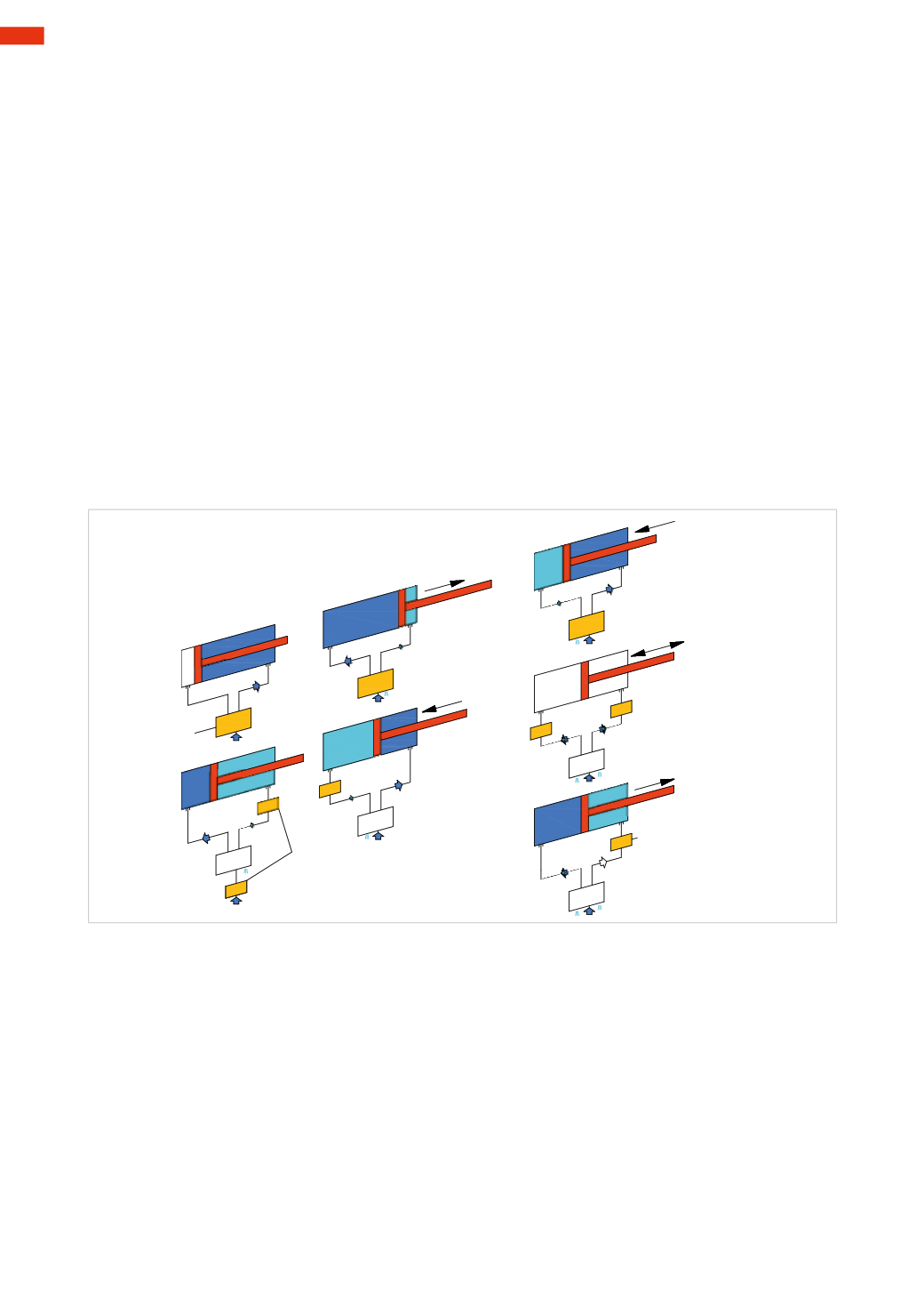
Figure 1
Phase A: directional
These valves open, close or divert the flow of compressed air, so that the cylinder assumes a different positionwith
respect to past position.
Phase B: flow or Pressure Regulation
These valves alter the physical characteristics of the compressed air. The adjustment can be made either on the
pressurewith “pressure regulation valves”, or on the flowwith “flow control valves”. To adjust the speed of one or
both strokes of the cylinder, it is necessary to insert the flow control valve between the distribution valve and the
cylinder. By varying the amount of compressed air in the exhaust, the time needed to empty the chambers of the
cylinder increases or decreases respectively. The pressure regulation valve is located at the inlet of the distribution
valve and is used to regulate the force of the cylinder.
Phase C: interception
These valves block and/ormodify the path of compressed air. The valve can prevent the passage of compressed air,
keeping it blocked inside the chamber or divert the passage, enabling a quicker way of exhaust.
A
B
C
Fig. 1
Classification of the valves
The choice of a valve depends on several parameters; such as the number of positions, ways and method of
activation/piloting.
Numbers are used in the classification of valves to identify the number of ways and positions. For example, the
term
3/2
indicates a
3
-way,
2
-position valve. The first digit represents the number of
ways
, usually 2, 3 or 5, the
second indicates the number of
positions
, usually 2 or 3.
The valves are depictedby a graphical pneumatic symbol,whereby each position a valve can assume is represented
by a square. A valve with two positions is indicated by two illustrative squares adjoined and a valve with three
positions has three squares adjoined.
4
90
CAMOZZI
>
VALVES