


 87 / 218

CYLINDERS
Hydrochecks
The seals of the pneumatic cylinders may not be fully compatible with the oil used in hydraulic brakes, for this
reason, the hydrochecks are independent of the pneumatic cylinder.
The hydrocheck consists of a cylinder with a relative compensation tank and can be equipped with:
Flow regulators, for adjusting the speed in:
• thrust
• traction
• or in both directions.
Valves:
• Skip (for maximum acceleration)
• Stop (for blocking the movement)
Both of these valves, by-pass the speed settings.
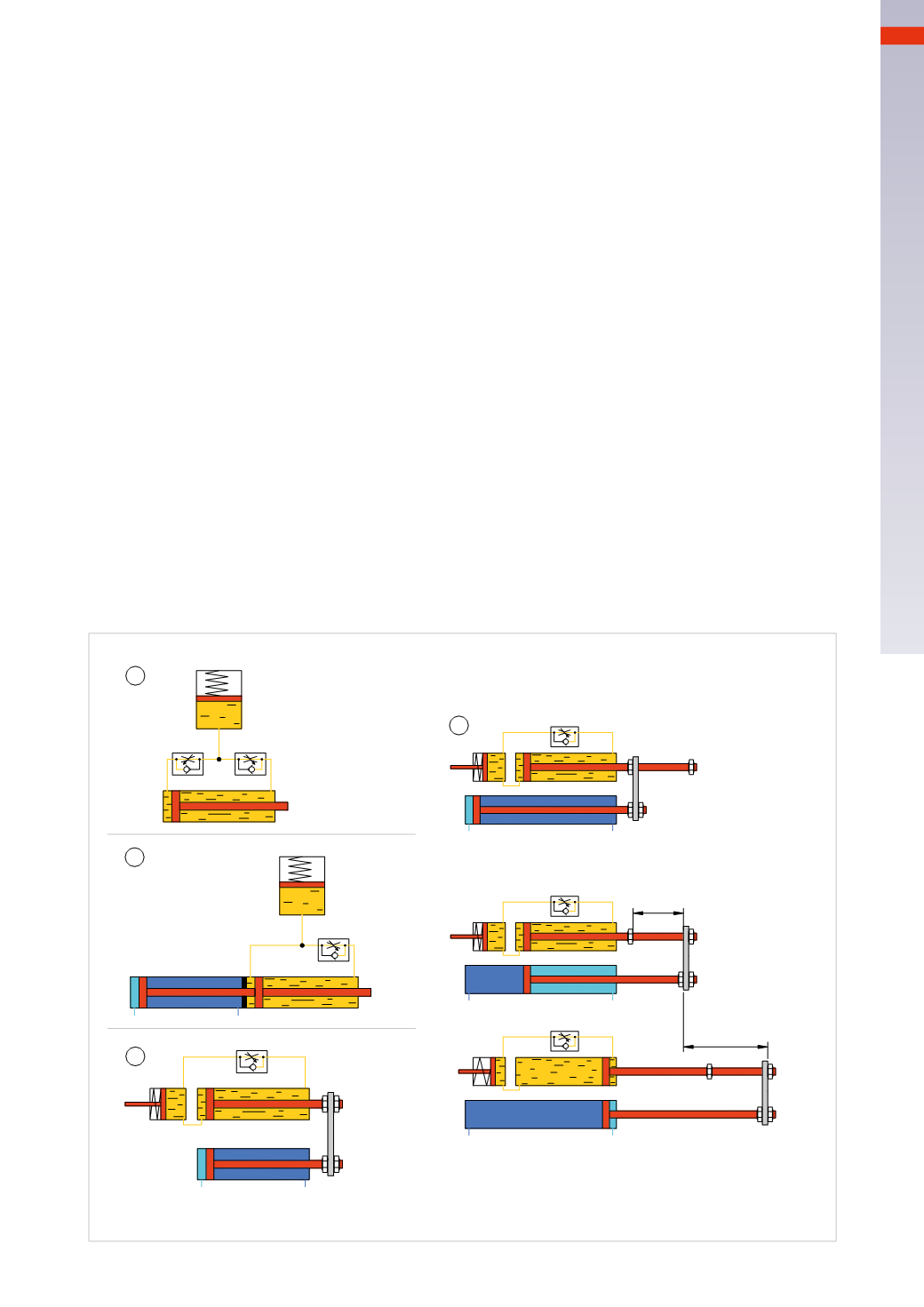
Figure 40
Pos. 1
: the oil present in the two chambers is located in a closed circuit and flow control valves allow the possibility
of adjusting the speed in both directions. The reserve of oil in the container compensates for the difference in volume
existing between the front and rear chamber of the hydrocheck.
Pos. 2
: example of connection of the hydrocheck with a pneumatic actuator. The rods are mounted on the same axis.
Pos. 3
: example of connection of the hydrocheck with a pneumatic actuator. The rods are parallel.
Pos. 4
: example of adjusting the speed of advancement from the tip of a drill.
The approach stroke to the work piece to be drilled is rapid, the drilling operation is slow and regulated.
A:
the rod is at the negative end-stroke
B:
the piston rod of the pneumatic cylinder has covered the approach stroke (this length of the stroke is adjustable
by means of regulation nuts) without the adjustment of the hydrocheck.
C:
from this position and throughout the rest of the stroke, the two rods move together. The pneumatic cylinder is
the “engine”, the unidirectional flow regulation valve mounted on the hydrocheck regulates the speed during
the drilling phase. This speed regulation, being made with a non-compressible fluid (oil) is more precise than a
pneumatic alternative.
On the return stroke, the piston rod of the pneumatic cylinder also re-positions the rod of the hydrocheck.
approach stroke
stroke
1
2
3
4
A
B
C
Fig. 40
3
85
CAMOZZI
>
CYLINDERS