


 93 / 218

VALVES
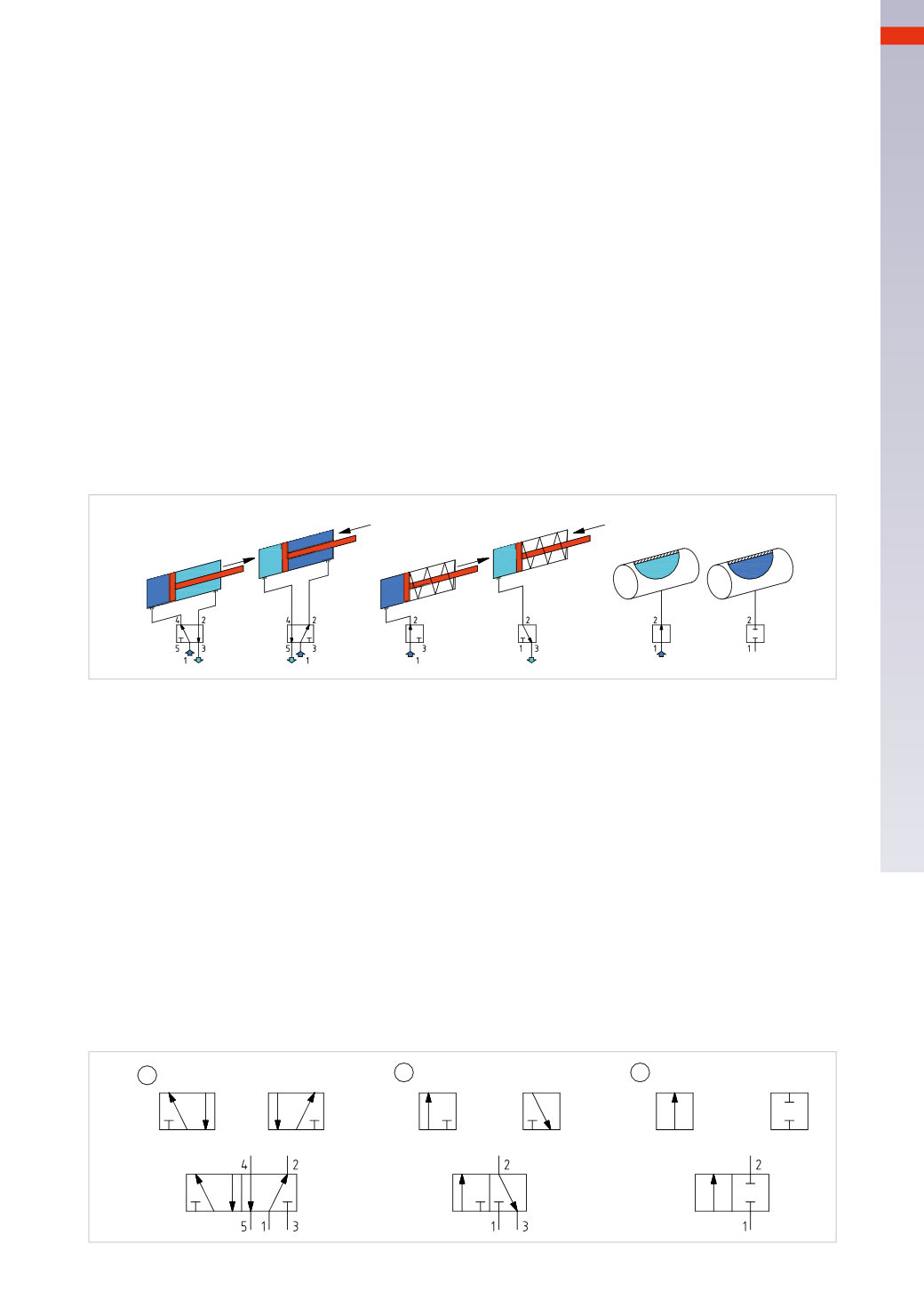
Figure 2
Movement of a double acting cylinder.
Phase A:
the arrowwith the apex pointing upwards indicates the compressed air supplied to inlet 1 of the valve is
directed towards the outlet 4 connected to the positive chamber (dark blue colour) of the cylinder. The arrowwith
apex pointing downwards indicates that the compressed air present in the negative chamber (blue colour) of the
cylinder through the valve from the outlet 2will direct towards the exhaust 3.
Phase B:
the arrow with apex pointing upwards indicates the compressed air supplied to inlet 1 of the valve is
directed towards the outlet 2 attached to the negative chamber (dark blue colour) of the cylinder. The arrowwith
apex pointing downwards indicates the movement of the compressed air present in the positive chamber (blue
colour) of the cylinder through the valve from the outlet 4will direct towards the exhaust 5.
Single Acting Cylinder.
PhaseC:
the arrowwith the apex pointing upwards indicates that the compressed air supplied to the inlet 1 of the
valve is directed towards the outlet 2 connected to the positive chamber (dark blue colour) of the cylinder.
Phase D:
the chamber previously under pressure must be discharged; we can use a valve with fewer ways than
in the previous case.
Pressurization of a tank.
Phase F:
the arrowwith the apex pointing upwards indicates that the compressed air supplied to input 1 of the
valve is directed towards the outlet 2 connected to the tank.
Phase G:
the arrow has been replaced by a plug, there is no passage of compressed air from inlet 1 to outlet 2,
the tank remains pressurised.
A
B
C
F
D
G
Fig. 2
Each square contains symbols; the arrow represents the direction of the compressed air flow in that particular
position, the “T” represents the blockage of the air passage in that position.
The symbol gives no indication of the size.
Figure 3
Pos. 1: 5/2
-way valve
The squares
A
and
B
indicate the two positions that the valve can assume, the direction of flow is indicated by the
arrows. In addition to the indicated direction of the flow, and regardless of the number of positions, the arrows also
indicate the number of connections to the valves, their definition is:
Connection
1 inlet
of the compressed air
Connection
2 outlet
predefined or at rest
Connection
3 exhaust
port of outlet 2
Connection
4 outlet
obtained by controlling the valve
Connection
5 exhaust
port of outlet 4
Pos. 2: 3/2
-way valve
The squares
C
and
D
represent the two distinct valve positions.
Connection
1 inlet
of the compressed air
Connection
2 outlet
Connection
3 exhaust port
of outlet 2
Pos. 3: 2/2
-way valve
The squares
F
and
G
represent the two distinct valve positions.
Connection
1 input
of the compressed air
Connection
2 outlet
Fig. 3
A
B
C
D
F
G
1
2
3
4
91
CAMOZZI
>
VALVES