


 111 / 210

102
2
SHORT FORM CATALOGUE
>
Release 8.8
2
CONTROL
Products designed for industrial applications.
General terms and conditions for sale are available on
www.camozzi.com.CONTROL >
Series HN valve islands
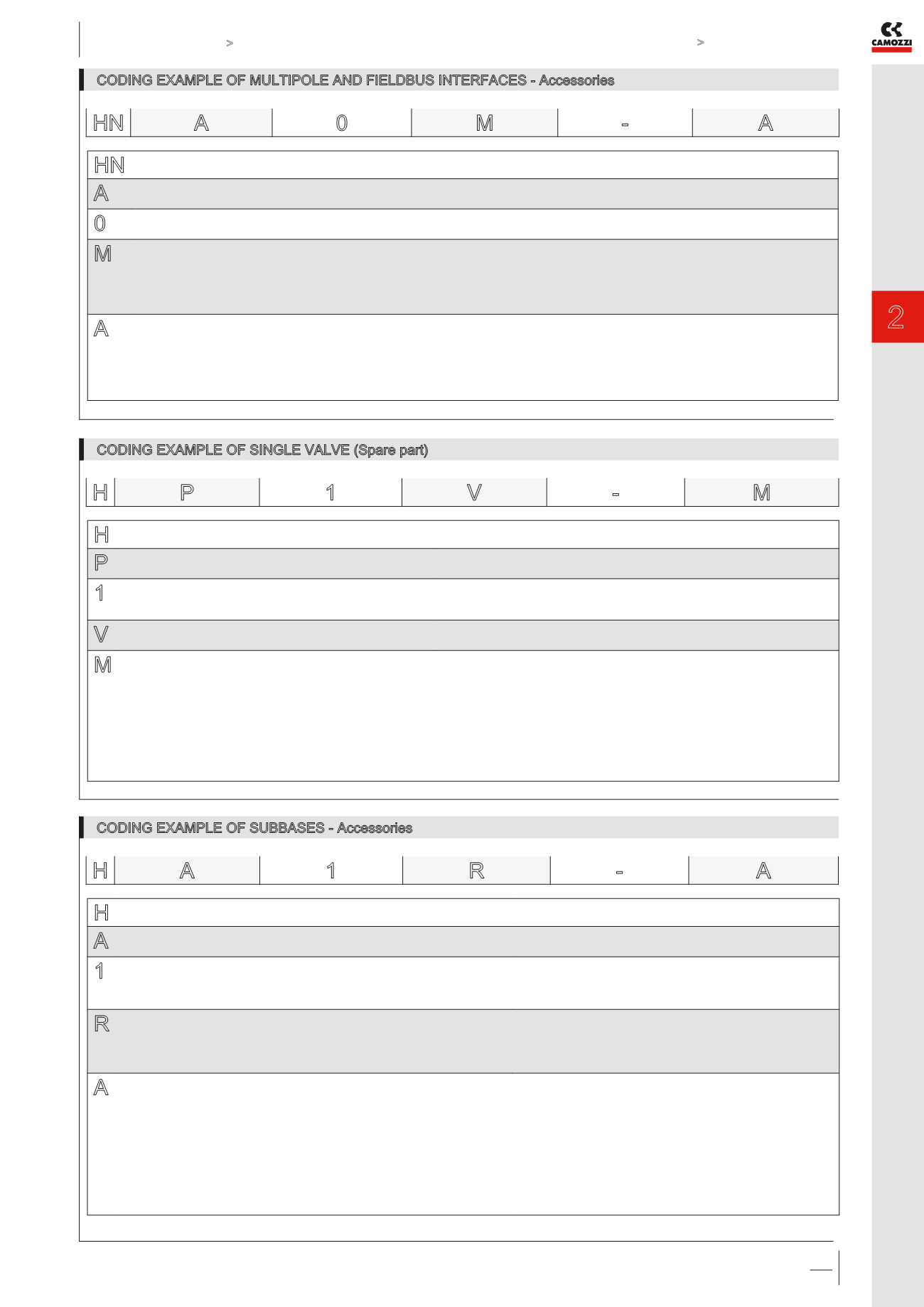
CODING EXAMPLE OF MULTIPOLE AND FIELDBUS INTERFACES - Accessories
HN
SERIES
A
TYPE:
A = Accessory
0
SIZE:
0 = not defined
M
ELECTRICAL CONNECTION:
M = 25 pin PNP Multipole
N = 25 pin NPN Multipole
H = 37 pin PNP Multipole
L = 37 pin NPN Multipole
I = HN interface with Series CX
A
TERMINALS:
A = 1, 12/14 in common - 3/5, 82/84 with thread
B = 1, 12/14 separated - 3/5, 82/84 with thread
C = 1, 12/14 in common - 3/5, 82/84 with silencer
D = 1, 12/14 separated - 3/5, 82/84 with silencer
NOTE: The Right Terminal is supplied with seals and fixing screws and available as accessory with the commercial code HA0T-H
Detailed descriptions of the available accessories can be found in the valve island catalogue
HN A
0
M
-
A
CODING EXAMPLE OF SINGLE VALVE (Spare part)
H
SERIES
P
TYPE:
P = pneumatic
1
SIZE:
1 = 10.5
2 = 21
V
TYPE OF ACCESSORY:
V = Solenoid valve
M
SOLENOID VALVE:
M = 5/2 Monostable
B = 5/2 Bistable
V = 5/3 Centres Closed
C = 2 x 3/2 NC
A = 2 x 3/2 NO
G = 1 x 3/2 NC + 1 x 3/2 NO
E = 2 x 2/2 NC
F = 2 x 2/2 NO
I = 1 x 2/2 NC + 1 x 2/2 NO
L = free position
SOLENOID VALVE + REGULATOR + SUBBASE
N = 5/2 Monostable
P = 5/2 Bistable
Q = 5/3 Centres Closed
R = 2 x 3/2 NC
S = 2 x 3/2 NO
T = 1 x 3/2 NC + 1 x 3/2 NO
U = 2 x 2/2 NC
X = 2 x 2/2 NO
Y = 1 x 2/2 NC + 1 x 2/2 NO
Detailed descriptions of the available accessories can be found in the valve island catalogue
H P
1
V
-
M
CODING EXAMPLE OF SUBBASES - Accessories
H
SERIES
A
TYPE:
A = accessories
1
SIZE:
0 = for X-Y-K-T-U-V-Z
1 = 10.5
2 = 21
R
TYPE OF ACCESSORY:
R = subbase for multipole connection
G = seal
W = subbase without electronic board (option valid only for position 2a)
See the components list in the valve island catalogue
A
SUBBASE:
A = through - M7 threads
AZ = through - M7 threads, monostable
D = channel 1, 3, 5 closed - M7 threads
DZ = channel 1, 3, 5 closed - M7 threads, monostable
G = channel 3, 5 closed - M7 threads
GZ = channel 3, 5 closed - M7 threads, monostable
Q = through - G1/8 threads
X = supplementary supply and exhaust
Y = supplementary supply and exhaust with integrated silencer
W = supply from the exhausts
K = separation of electrical supply and supplementary pneumatic supply
SEAL:
T = diaphragm seal for the closure of channels 1, 3, 5
U = diaphragm seal for the closure of channel 1
V = diaphragm seal for the closure of channels 3, 5
P = through
NOTE: subbases are always supplied without connection fittings
Detailed descriptions of the available accessories can be found in the components list on the valve island catalogue
H A
1
R
-
A