


 76 / 210

67
2
SHORT FORM CATALOGUE
>
Release 8.8
2
CONTROL
Products designed for industrial applications.
General terms and conditions for sale are available on
www.camozzi.com.CONTROL >
Accessories for solenoid valves
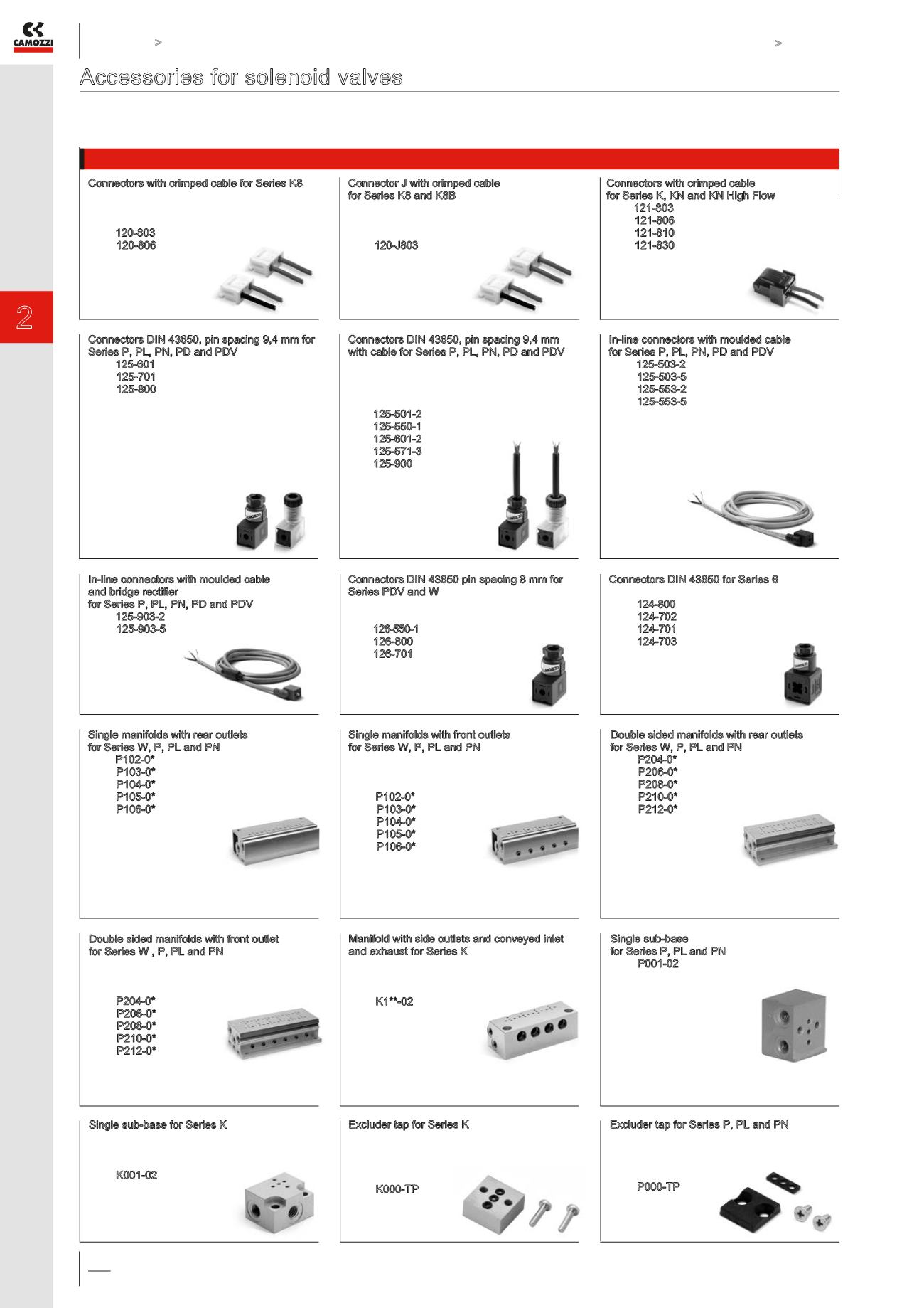
Accessories for solenoid valves
Connectors, manifolds, bases, sub-bases and blanking plates
Single manifolds with rear outlets
for Series W, P, PL and PN
Mod. P102-0* (2 positions)
P103-0* (3 positions)
P104-0* (4 positions)
P105-0* (5 positions)
P106-0* (6 positions)
Single manifolds with front outlets
for Series W, P, PL and PN
This manifold is arranged to be fixed through
DIN 46277/3 guide together with the accessory
PCF-E520
Mod. P102-0* (2 positions)
P103-0* (3 positions)
P104-0* (4 positions)
P105-0* (5 positions)
P106-0* (6 positions)
Manifold with side outlets and conveyed inlet
and exhaust for Series K
Note: use solenoid valves
with mounting screws on metal interfaces
(see the CODING EXAMPLE TABLE of Series K)
Mod. K1**-02
** = N° of positions
Excluder tap for Series P, PL and PN
Supplied with:
1x excluder tap,
1x interface seal,
2x screws
Mod. P000-TP
Double sided manifolds with rear outlets
for Series W, P, PL and PN
Mod. P204-0* (4 positions)
P206-0* (6 positions)
P208-0* (8 positions)
P210-0* (10 positions)
P212-0* (12 positions)
Single sub-base
for Series P, PL and PN
Mod. P001-02
Excluder tap for Series K
Supplied with:
1x excluder tap
1x interface seal
2x screws
Mod. K000-TP
Double sided manifolds with front outlet
for Series W , P, PL and PN
This manifold is arranged to be fixed through
DIN 46277/3 guide together with the accessory
PCF-E520
Mod. P204-0* (4 positions)
P206-0* (6 positions)
P208-0* (8 positions)
P210-0* (10 positions)
P212-0* (12 positions)
Single sub-base for Series K
Note: use solenoid valves
with mounting screws on metal interfaces
(see the CODING EXAMPLE TABLE of Series K)
Mod. K001-02
Connectors with crimped cable for Series K8
Cable section: 0.25 mm²
Cable external diameter: 1.2 mm
Material for the cable insulation: PVC
Mod. 120-803 (cable 300 mm)
120-806 (cable 600 mm)
Connectors DIN 43650, pin spacing 9,4 mm for
Series P, PL, PN, PD and PDV
Mod. 125-601
125-701
125-800
In-line connectors with moulded cable
and bridge rectifier
for Series P, PL, PN, PD and PDV
Mod. 125-903-2 (cable 2000 mm)
125-903-5 (cable 5000 mm)
Connector J with crimped cable
for Series K8 and K8B
Cable section: 0.25 mm²
Cable external diameter: 1.2 mm
Material for the cable insulation: PVC
Mod. 120-J803 (cable 300 mm)
Connectors DIN 43650 pin spacing 8 mm for
Series PDV and W
To be used in all DC valves with voltages
from 6 to 110 V
Mod. 126-550-1 (cable 1000 mm)
126-800
126-701
Connectors with crimped cable
for Series K, KN and KN High Flow
Mod. 121-803 (cable 300 mm)
121-806 (cable 600 mm)
121-810 (cable 1000 mm)
121-830 (cable 3000 mm)
In-line connectors with moulded cable
for Series P, PL, PN, PD and PDV
Mod. 125-503-2 (cable 2000 mm)
125-503-5 (cable 5000 mm)
125-553-2 (cable 2000 mm)
125-553-5 (cable 5000 mm)
Connectors DIN 43650 for Series 6
Protection class IP65
Mod. 124-800
124-702
124-701
124-703
Connectors DIN 43650, pin spacing 9,4 mm
with cable for Series P, PL, PN, PD and PDV
The internal rectifier circuit of the connector
Mod. 125-900 allows to use solenoid valves
with different AC voltage, even if the voltage
indicated on the solenoid valve is DC
Mod.125-501-2 (cable 2000 mm)
125-550-1 (cable 1000 mm)
125-601-2 (cable 2000 mm)
125-571-3 (cable 3000 mm)
125-900 (cable 2000 mm)
* = see the MANIFOLD PORTS
in the CODING EXAMPLE TABLE
of the reference Series
* = see the MANIFOLD PORTS
in the CODING EXAMPLE TABLE
of the reference Series
* = see the MANIFOLD PORTS
in the CODING EXAMPLE TABLE
of the reference Series
* = see the MANIFOLD PORTS
in the CODING EXAMPLE TABLE
of the reference Series