


 79 / 210

70
2
SHORT FORM CATALOGUE
>
Release 8.8
2
CONTROL
Products designed for industrial applications.
General terms and conditions for sale are available on
www.camozzi.com.CONTROL >
Series E
E
SERIES
5
FUNCTION:
5 = 5/2
6 = 5/3 Centres Closed
7 = 5/3 Centres Open
8 = 5/3 Centres in Pressure
2
SIZE:
2 = 10,5 mm
1
BODY TYPE:
1 = body with threaded plate
0 = body for sub-base
11
ACTUATION:
11 = electro-pneumatic, bistable
16 = electro-pneumatic, monostable
33 = pneumatic bistable - tube ø 3
36 = pneumatic monostable - tube ø 3
C33 = pneumatic bistable - tube ø 4
C36 = pneumatic monostable - tube ø 4
10
INTERFACE:
10
K
TYPE OF SOLENOID:
K
1
SOLENOID DIMENSION:
1 = 10x10
3
SOLENOID VOLTAGE:
1 = 6V DC
2 = 12V DC
3 = 24V DC
CODING EXAMPLE
E 5 2 1 -
11 -
10 -
K 1 3
CODING EXAMPLE
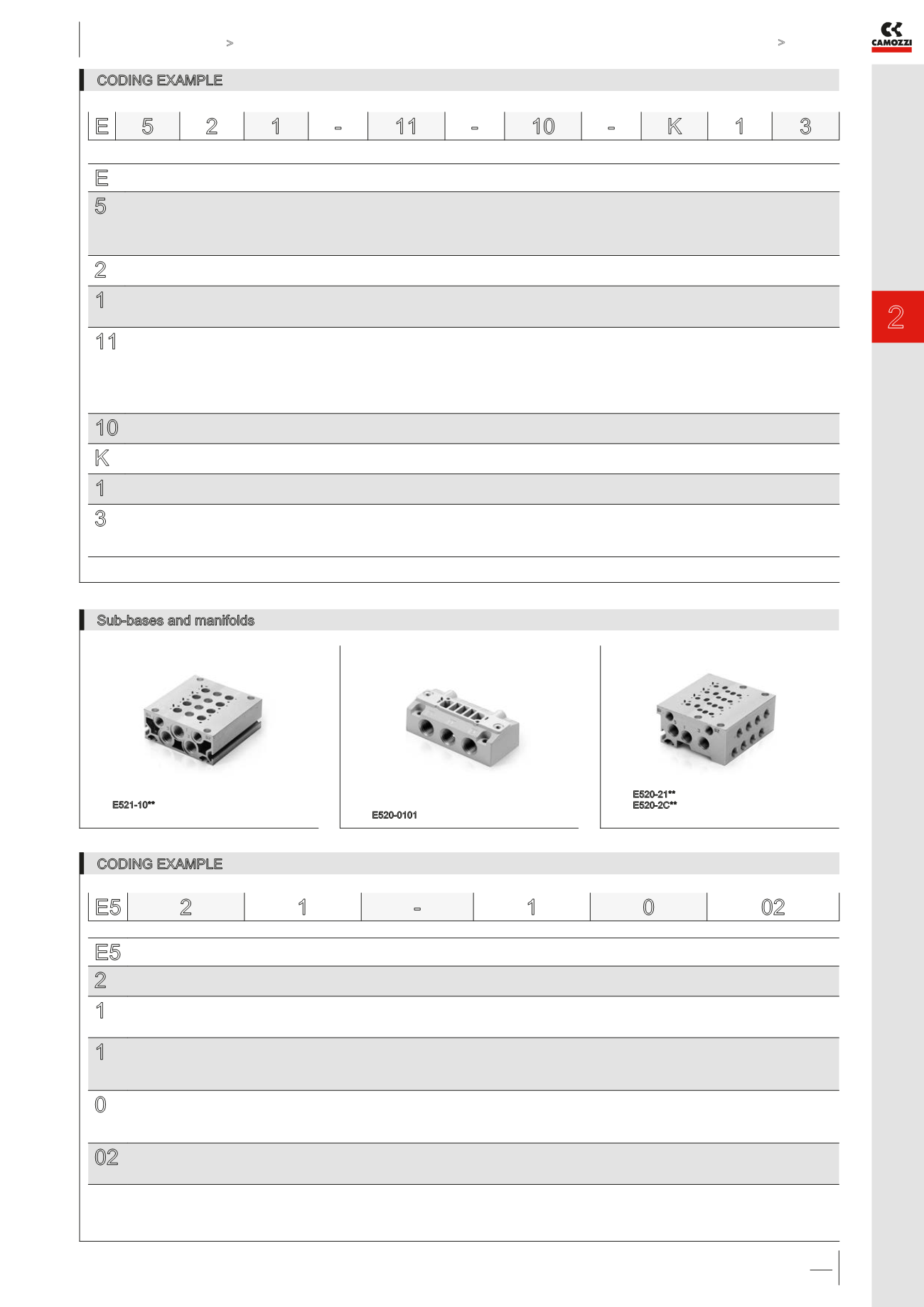
Sub-bases and manifolds
E5 2
1
-
1
0
02
E5
SERIES
2
SIZE:
2 = size 10,5
1
BODY TYPE:
0 = body for sub-base assembly
1 = body with threads or tube port
1
TYPE OF SUB-BASE:
0 = single sub-base with side outlets
1 = manifold for threaded valve
2 = manifold for body mounted valve
0
PORTS:
0 = for valves with outlets on the body
1 = threaded
C = tube 4
02
N° OF POSITIONS:
01 = single
03, 04, 06, 08, 10, 12 = multiple
NOTE: When constructing manifolds with 10 or more stations, it is recommended, in order to reduce the risk of pressure drop within the assembly, that pressure is supplied to port
1 at each end of the block. The exhaust ports 3 and 5 at each end should also be utilized (size 10,5 and 16 mm). The same provision should be made for 5 station manifolds of the
19 mm valves. Manifolds complete with ports for external pilot supply are available on request.
Mod. E521-10**
** = number of positions
Mod. E520-0101
Mod. E520-21**
E520-2C**
** = number of positions