
17
The company reserves the right to vary models and dimensions without notice.
These products are designed for industrial applications and are not suitable for sale to the general public.
FITTINGS NPTF
Fittings NPTF
1
NORTH AMERICAN FITTINGS & FLOW CONTROL VALVE CATALOG
>
Release 8.6
Fittings Mod. 6700...
Cartridge
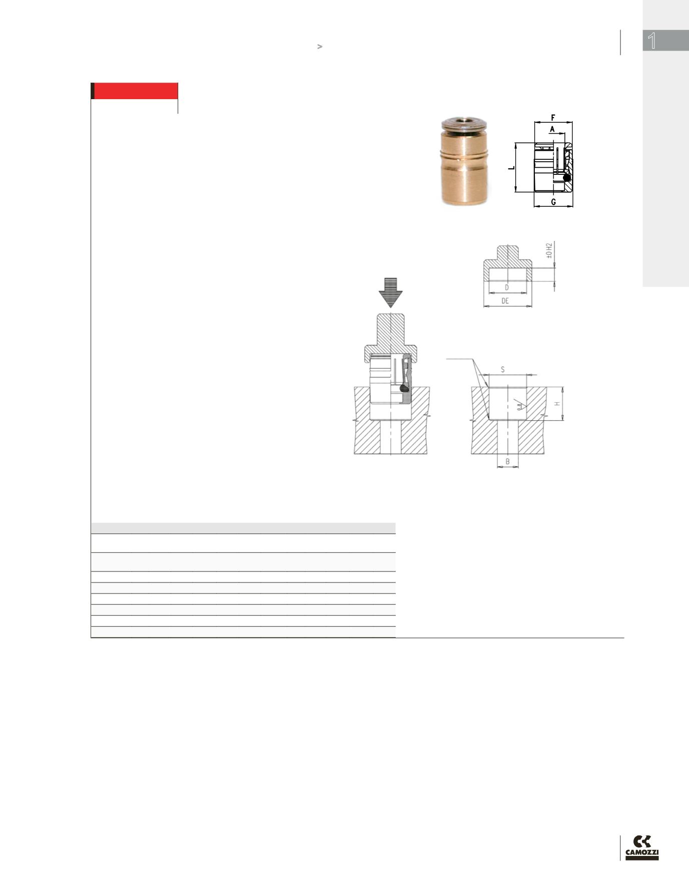
DIMENSIONS (in inches)
Insertion
Force
Mod.
A
OD
F G L
S H B Kg.
Min
Kg.
Max
D H2 DE
6700 02-00 1/8 0.339 0.346 0.571 0.344 0.453 0.138 200 360 0.347 0.129 0.551
6700 53-00 5/32 0.339 0.346 0.571 0.344 0.433 0.138 200 360 0.347 0.129 0.551
6700 04-00 1/4 0.465 0.472 0.669 0.470 0.472 0.158 160 570 0.472 0.149 0.669
6700 05-00 5/16 0.543 0.551 0.709 0.549 0.551 0.236 140 400 0.551 0.129 0.748
6700 06-00 3/8 0.622 0.630 0.807 0.628 0.649 0.315 150 650 0.630 0.138 0.827
6700 08-00 1/2 0.740 0.748 0.776 0.746 0.610 0.413 150 650 0.748 0.138 0.945
* Hole tolerances: +0, -0.002 (in.)
* For plastic (non-metal) manifolds, reduce all hole dimensions
“S” by 0.02 mm (0.001 in.)
* INSTALLATION: Drill or bore hole per specifications per size
of cartridge (dimensions H and S).
* Smooth or ream hole dimensions to hole tolerances.
* Simply press fit cartridge into hole with an evenly distributed
force over the top surface.
* Removal of the collet ring is not necessary.
* Cartridge fittings are useful for installations in various
manifolds and/or distribution blocks when drilling and tapping
are not desirable.
The Dimension ‘H2’ for the press-tool should be noted and followed,
which creates a specific mechanical stop. This serves the purpose of
avoiding, (in case of any excessive insertion force used), damage to the
collet body, shape or design. Without which, could lead to some damage
or distortion of the collet bite/release ring.
Surface Finish of the gland seat required : Ra </= 0.8 microns.
Final Fit and Finish requires that the top most ridge/bite-ring of the
cartridge body be at least 1 mm below the surface of the gland chamfer.
Gland Width “S” Tolerances
+ .0’’ / - .002’’ Metal Seat Tolerance
0.5 x 45
°
Chamfer Required
Insertion Force - KG


