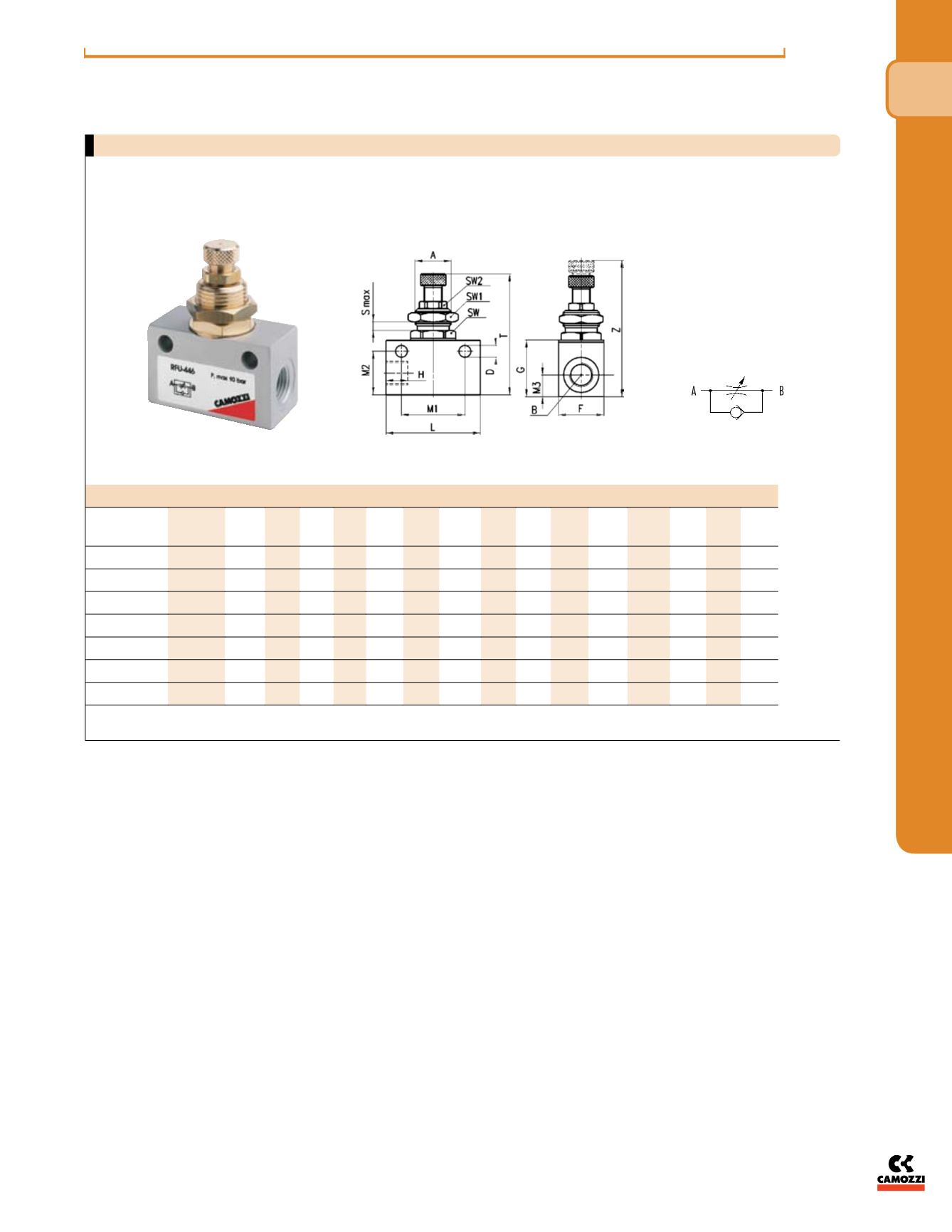

DIMENSIONS (in inches)
Mod.
A
B
H D F
G L
M1 M2 M3 T
Z SMax SW SW1 SW2
METRIC UNF
RFU 452-M5
M10x1 10-32 .256 .165 .551 .630 1.02 .728 .520 .280 1.54 1.750 .118 .472 .551 .315
NPTF
RFU 482-02
M12X1 1/8” .354 .177 .629 .826 1.338 .964 .649 .315 1.811 2.007 .157 .551 .669 .354
RFU 483-02
M12X1 1/8” .354 .177 .629 .826 1.338 .964 .649 .315 1.811 2.007 .157 .551 .669 .354
RFU 444-04
M20x1.5 1/4” .492 .255 .984 1.181 2.047 1.377 .944 .472 2.362 2.716 .275 .866 .944 .551
RFU 446-04
M20x1.5 1/4” .492 .255 .984 1.181 2.047 1.377 .944 .472 2.362 2.716 .275 .866 .944 .551
Unidirectional flow controller Series RFU
To regulate the speed of a cylinder, the air flow from the chamber which is being discharged must be regulated.
For this reason, the unidirectional flow controller must be connected as follows:
connect the threaded outlet marked A to the cylinder inlet and the threaded outlet marked B to the valve user port.
i n -l i n e f l ow con tro l v a l v e s
The company reserves the right to vary models and dimensions without notice.
These products are designed for industrial applications and are not suitable for sale to the general public.
141
N P T F/ I NCH
f l ow con t ro l v a l v e s & a c c e s sor i e s
4


