


 148 / 226

Operating pressure
1.0 - 10 bar, [14.5 - 145 psi]
Nominal pressure
6 bar, [87 psi]
Nominal flow
See graphs
Nominal diameter (Flow Orifice)
1/8” = 2 mm [.079”], or 3 mm [.118”]
1/4” = 4 mm [.157”], or 6 mm [.236”]
Valve group
Unidirectional controller, [meter-in, meter-out]
Construction
In-Line Needle type
Mounting
Through holes in body, or control panel
Materials
Aluminum body, Brass needle, Buna-N seals
Port sizes
M5 [10-32 UNF], 1/8”, 1/4”, NPTF
Installation
As required
Operating temperature
32° - 175° F, [dry air necessary down to -4° F]
Fluid
Filtered air
Lubricant
Oil compatible with Buna-N, [3° - 10° E]
TECHNICAL SPECIFICATIONS
PNEUMATIC DATA
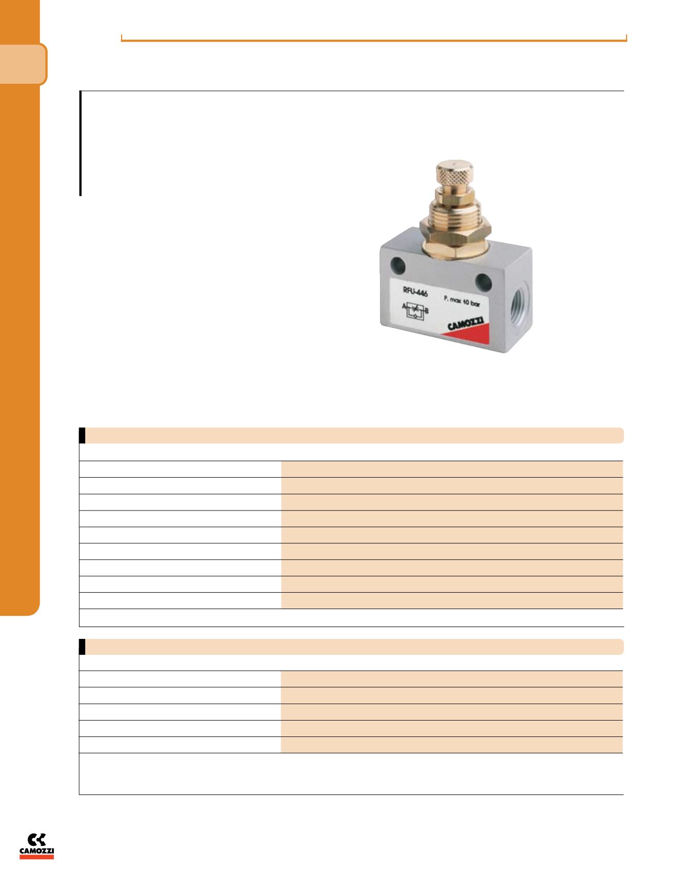
In-line Flow Control Valves Series RFU - NPTF/INCH
Panel or wall-mounted flow controllers
In-line/Unidirectional, RFU
Ports M5 [10-32 UNF],
1/8”, 1/4” NPTF
The undirectional flow controllers are
equipped with M5 [10-32 UNF], 1/8” and
1/4” ports, each of which is available with
two different types of adjustment (see dia-
grams).
They are used mainly for controlling
the speed of cylinders.
They may be mounted on control panels
or cylinders, as required.
*Qn flowrate [SCFM] determined with a supply pressure of 6 bar, [87 psi], and with a pressure drop of 1 bar, [14.5
psi].
**Dimensions are in inches
i n - l i n e f l ow con t ro l v a l v e s
The company reserves the right to vary models and dimensions without notice.
These products are designed for industrial applications and are not suitable for sale to the general public.
138
N P T F/ I NCH
f l ow con t ro l v a l v e s & a c c e s sor i e s
4