
f l ow con t ro l v a l v e s & a c c e s sor i e s
4
b s p/me t r i c
The company reserves the right to vary models and dimensions without notice.
These products are designed for industrial applications and are not suitable for sale to the general public.
157
B S P / M E T R I C
Dimensions in millimeters (mm)
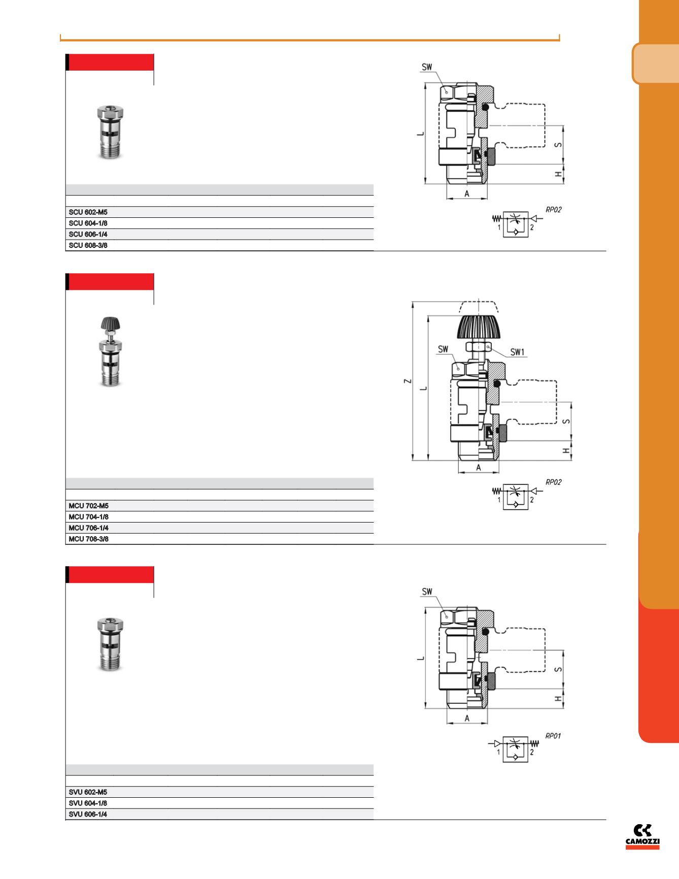
Valves Series SCU
Unidirectional flow controller for mounting on single-
acting or double-acting cylinders.
Adjustment of setting by a screwdriver.
Ports: M5, G1/8, G1/4 and G3/8.
Assembly with fittings Mod. 6610; 6620; 1610; 1620;
2023; 1170.
DIMENSIONS
Mod.
A
H
L
S
SW
SCU 602-M5
M5
3,5
21,5
5,5
8
SCU 604-1/8
G1/8
5
31,5
12,5
12
SCU 606-1/4
G1/4
6
32,5
12,5
15
SCU 608-3/8
G3/8
7
40,5
12,5
18
Note: M5 flow controllers must be
used together with M6 adjustable
fittings.
Valves Series MCU
Unidirectional flow controller for mounting on single-
acting or double-acting cylinders.
Adjustment of setting by a manually operated
knurled screw.
Ports: M5, G1/8, G1/4, G3/8.
Assembly with fittings Mod. 6610; 6620; 1610; 1620;
2023; 1170.
DIMENSIONS
Mod.
A
H
L
S
SW SW1
Z
MCU 702-M5
M5
3,5
31
5,5
8
5,5
35
MCU 704-1/8
G1/8
5
41
12,5
12
7
46
MCU 706-1/4
G1/4
6
43,5
12,5
15
7
49
MCU 708-3/8
G3/8
7
52,5
12,5
18
10
60,5
Valves Series SVU
Unidirectional flow controller for mounting on valves.
Adjustment of setting by a screwdriver.
Ports: M5, G1/8, G1/4.
Assembly with fittings Mod. 6610; 6620; 1610; 1620;
2023; 1170.
DIMENSIONS
Mod.
A
H
L
S
SW
SVU 602-M5
M5
3,5
21,5
5,5
8
SVU 604-1/8
G1/8
5
31,5
12,5
12
SVU 606-1/4
G1/4
6
32,5
12,5
15
Note: M5 flow controllers must be
used together with M6 adjustable
fittings.
Note: M5 flow controllers must be
used together with M6 adjustable
fittings.


