
f l ow con t ro l v a l v e s & a c c e s sor i e s
4
B S P / M E T R I C
b s p/me t r i c
The company reserves the right to vary models and dimensions without notice.
These products are designed for industrial applications and are not suitable for sale to the general public.
158
Dimensions in millimeters (mm)
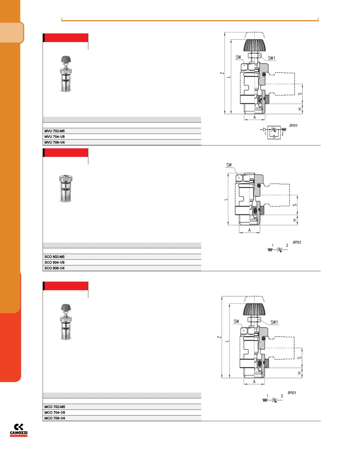
Valves Series MVU
Unidirectional flow controller for mounting on valve.
Adjustment of setting by a manually operated
knurled screw.
Ports: M5, G1/8, G1/4.
Assembly with fittings Mod. 6610; 6620; 1610; 1620;
2023; 1170.
DIMENSIONS
Mod.
A
H
L
S
SW SW1
Z
MVU 702-M5
M5
3,5
31
5,5
8
5,5
35
MVU 704-1/8
G1/8
5
41
12,5
12
7
46
MVU 706-1/4
G1/4
6
43,5
12,5
15
7
49
Note: M5 flow controllers must be
used together with M6 adjustable
fittings.
Valves Series SCO
Bidirectional flow controller.
Adjustment of setting by a screwdriver.
Ports: M5, G1/8, G1/4.
Assembly with fittings Mod. 6610; 6620; 1610; 1620;
2023; 1170; 2905.
DIMENSIONS
Mod.
A
H
L
S
SW
SCO 602-M5
M5
3,5
21,5
5,5
8
SCO 604-1/8
G1/8
5
31,5
12,5
12
SCO 606-1/4
G1/4
6
32,5
12,5
15
Valves Series MCO
Bidirectional flow controller.
Adjustment of setting by a manually operated
knurled screw.
Ports: M5, G1/8, G1/4.
Assembly with fittings Mod. 6610; 6620; 1610; 1620;
2023; 1170; 2905.
DIMENSIONS
Mod.
A
H
L
S
SW SW1
Z
MCO 702-M5
M5
3,5
31
5,5
8
5,5
35
MCO 704-1/8
G1/8
5
41
12,5
12
7
46
MCO 706-1/4
G1/4
6
43,5
12,5
15
7
49
Note: M5 flow controllers must be
used together with M6 adjustable
fittings.
Note: M5 flow controllers must be
used together with M6 adjustable
fittings.


