


 34 / 226

Valve group
3-way/2-position
Construction
Shuttle slide
Mounting
In/line thread ports
Materials
Nickel-Plated brass body, Buna-N seals
Threaded port sizes
M5, 1/8”, 1/4”, 3/8”, 1/2” 3/4" NPTF
Installation
In-line
Operating temperature
32°F - 175°F, (dry air necessary down to 14° F)
Fluid
Filtered air
Lubricant
Not required; otherwise oil compatible with Buna-N, (3°- 10° E) (ISOVG32 grade: 32 centistrokes)
Operating pressure
0 - 10 bar (0 - 145 psi))
Nominal pressure
6 bar (87 psi)
Nominal flow
*Qn Series VMS: P
→
A M5 = 140 NL/min (4.9 SCFM)
1/8” = 600 NL/min (21.2 SCFM)
1/4” = 1200 NL/min (42.4 SCFM)
3/8” = 2100 NL/min (74.1 SCFM)
1/2” = 3350 NL/min (118.5 SCFM
3/4” = 5350 NL/min (189 SCFM
A
→
R M5 = 145 NL/min (5.12 SCFM)
1/8” = 740 NL/min (26.2 SCFM)
1/4” = 1780 NL/min (62.9 SCFM)
3/8” = 1830 NL/min (64.7 SCFM)
1/2” = 4030 NL/min (142.5 SCFM)
3/4” = 5000 NL/min (176.8 SCFM)
Cv Rating (Inlet flow)
Series VMS:
M5 = 0.15
1/8” = 0.63
1/4” = 1.26
3/8” = 2.21
1/2” = 3.53
3/4” = 5.62
*Qn flowrate (SCFM) determined with a supply pressure of 6 bar (87 psi), and with a pressure drop of 1 bar (14.5 psi).
Exhausting flowrate (A
→
R), determined with an inlet pressure of 6 bar (87 psi), while exhausting to atmosphere.
The company reserves the right to vary models and dimensions without notice.
These products are designed for industrial applications and are not suitable for sale to the general public.
24
m a n u a l v a l v e s
1
Dimensions in millimeters (mm)
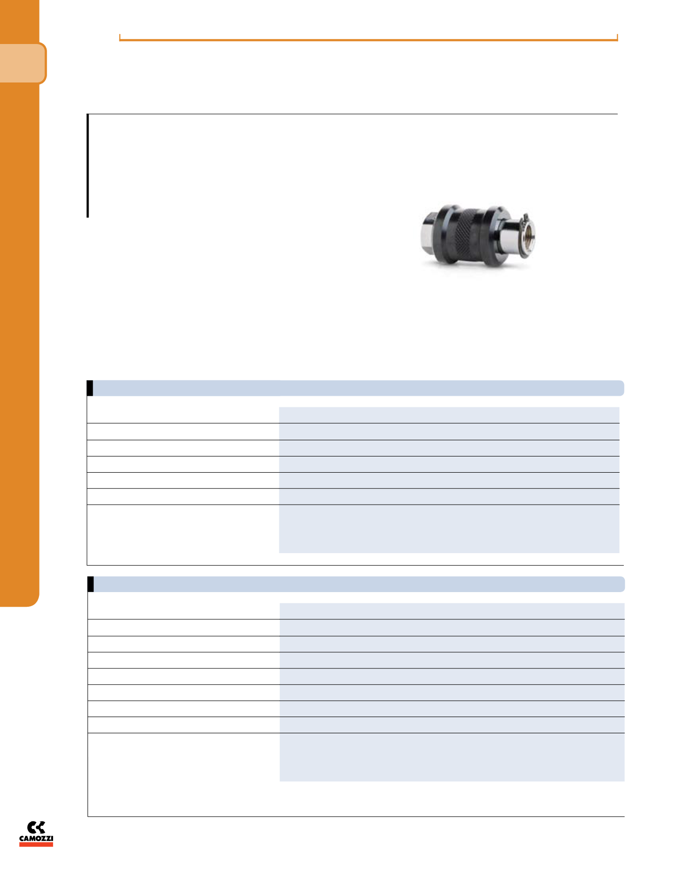
Series VMS
Cv = .73 - 4.10
Slide Valve
Series VMS, 3-way/2-position
Ports M5, 1/8”, 1/4”, 3/8”, 1/2”, 3/4" NPTF
The VMS series slide valves are commonly
used upstream of FRL units to ease repair and
replacement. They can also be used in
situations requiring the exhausting of
all downstream air. This would assist in
maintenance applications where ball valves
may be too large and bulky
to maneuver in tight assembly spaces. The
exhausting of downstream air while
simultaneously blocking inlet flow helps in
building component groups to be tested in
stages, and assembled later onto the main
body of a machine.
TECHNICAL SPECIFICATIONS
PNEUMATIC DATA
Cv = .73 - 4.10