
CATALOGUE >
Release 8.8
APPENDIX >
Technical information about products
a
APPENDIX
Symbols description
Dimensioning guide: formulas and examples
Symbol
Unit
Description
m
friction coefficient
a
(rad)
angle of incline
q
(rad)
side load angle
w
(rad/s)
angular velocity
A
(m)
width
B
(m)
thickness
C
(/hr)
impact cycles per hour
D
(cm)
cylinder diameter
d
(cm)
piston rod diameter
E
d
(Nm)
drive energy per cycle
E
k
(Nm)
kinetic energy per cycle
E
t
(Nm)
total energy per cycle
E
tc
(Nm)
total energy per hour
F
(N)
propelling force
Symbol
Unit
Description
Fm (N)
maximum shock force
g
(m/s
2
)
gravity acceleration (9.81 m/s
2
)
h
(m)
hight
m
(kg)
mass to be decelerated
Me
(kg)
effective mass
P
(bar)
operating pressure
R
(m)
radius
Rs
(m)
shock absorber mounting distance
from rotation center
S
(m)
stroke (shock absorber)
T
(Nm)
driving torque
t
(s)
deceleration time
v
(m/s)
velocity of impact mass
vs
(m/s)
impact velocity at shock absorber
In order to select the correct dimensions of Shock absorbers the following
parameters are needed:
- Weight of the impact object
m (kg)
- Impact speed
v
(m/s)
- Propelling or thrust force
F
(N)
- No. of impact cycles per hour C (/hr)
Some formulas
5. Cylinder’s traction force
F = D
2
· π
· P · g/100
4
6. Cylinder’s thrust force
F = (D
2
- d
2
) · π
· P · g/100
4
7. Maximum shock force (approx.)
Fm = 1.2 E
t
/S
8. Total energy consumption per hour
E
tc
=
E
t
· C
9. Mass
Me = 2E
t
/v
2
Some formulas
1. Kinetic energy
E
k
= mv
2
/2
2. Drive energy
E
d
= F · S
3. Total energy
E
t
= E
k
+E
d
4. Free fall speed
v = √ (2g*h)
Calculation:
Example 1: Horizontal impact
Application data:
v = 1.0 m/s
m = 50 kg
S = 0.01 m
C = 1500 cycles/h
The adequate Shock Absorber to use in this case is Mod. SA 2015
according to the technical data where we find that E
t
(max) = 59 Nm,
E
tc
(max) = 38000 Nm/h and Me (max) = 120 kg.
E
k
= mv
2
= 50 . 1
2
= 25 Nm
2 2
E
t
= Ek = 25 Nm
E
tc
=
E
t
. C = 25 . 1500 = 37500 Nm/h
Me = 2
E
t
= 2 . 25 = 50 kg
v
2
1
2
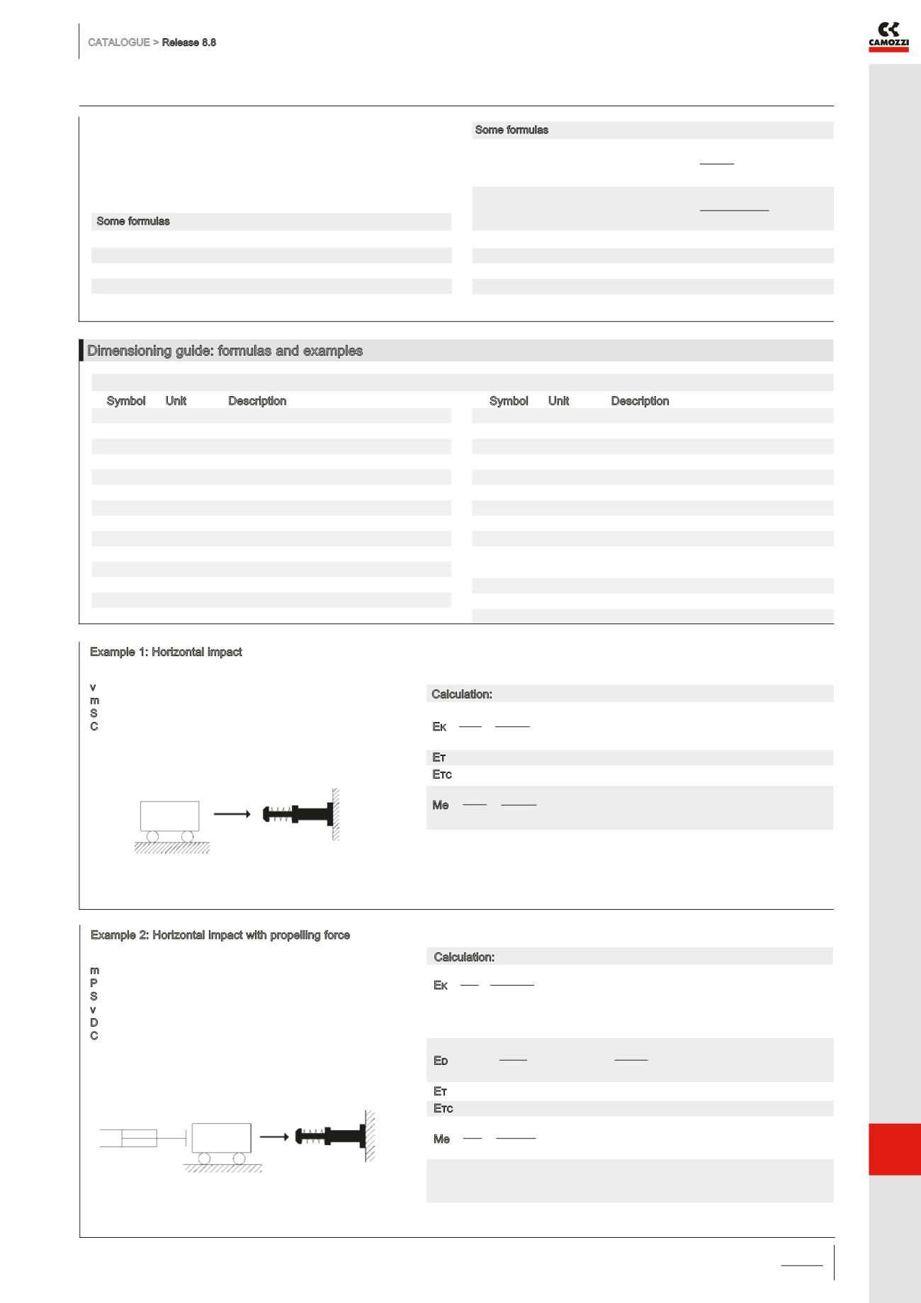
Example 2: Horizontal impact with propelling force
Application data:
m = 40 kg
P = 6 bar
S = 0.01 m first hypothesis SA 1210
v = 1.2 m/s
D = 50 mm
C = 780 cycles/h
To facilitate the calculation, the pressure in the empty
cylinder chamber is not considered (safety condition)
Calculation:
The adequate Shock Absorber to use in this case is Mod.SA 2015
according to the technical data where we find that E
t
(max) = 59 Nm,
E
tc
(max) = 38000 Nm/h and Me (max) = 120 kg.
E
k
= mv
2
= 40 . 1,2
2
= 28,8 Nm
2 2
Consider the shock absorber with the lowest E
t
but superior to 28.8 Nm:
mod. SA 2015 S=0.015 m
E
d
= F . S = D
2
.
π . P . g/100 . S = 50
2
. π . 6 . 9,81/100 . 0,015 = 17,3 Nm
4
4
E
t
= E
k
+ E
d
= 28,8 + 17,3 = 46,1 Nm
E
tc
= E
t
. C = 46,1 . 780 = 35958 Nm/h
Me = 2E
t
= 2 . 46,1 = 64,0 Kg
v
2
1,2
2
a
/3.05
Dimensioning guide for Shock Absorbers Series SA


