
f l ow con t ro l v a l v e s & a c c e s sor i e s
4
b s p/me t r i c
The company reserves the right to vary models and dimensions without notice.
These products are designed for industrial applications and are not suitable for sale to the general public.
169
B S P / M E T R I C
Dimensions in millimeters (mm)
6512
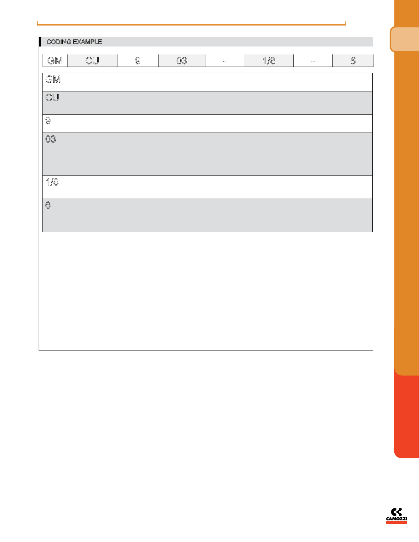
CODING EXAMPLE
GM CU
9
03
-
1/8
-
6
GM
ACTUATION:
GM = manual
GS = screwdriver
CU
ASSEMBLY:
CU = on cylinders unidirectional
VU = on valves unidirectional
CO = bidirectional
9
VERSIONS:
8 = needle (screwdriver operated)
9 = needle (manually operated)
03
FLOW CONTROL RANGE:
size ø tube
13 = 1.5 3
14 = 1.5 4
03 = 3.5 6
04 = 3.5 8
05 = 5 8
06 = 5 10
1/8
PORTS:
M5
1/8
1/4
6
Ø TUBE:
3
4
6
8
10
To ensure the right choice of unidirectional flow controller, proceed as follows: calculate the quantity of air in Nl/min (see cylinder Table); determine the stroke time of the cylinder;
refer to graph to see which controller is the right type.


