


 210 / 218

1
2
A
A+ / B+ / A- / B-
B
a0 a1
b0 b1
B1
B2 B3
B4
1 2 3
4 5
1
2
3
4
5
a1
x
a0
b1
a1 x
y y1
a0
b1
b0
b0
I.C.
I.C.
F.C.
F.C.
X B 1 B 3 B 2 B 4
X
Y
B 1 B 3 B 2 B 4
6
EM
Reset
NO/2
NO/2
NO4/5
EM
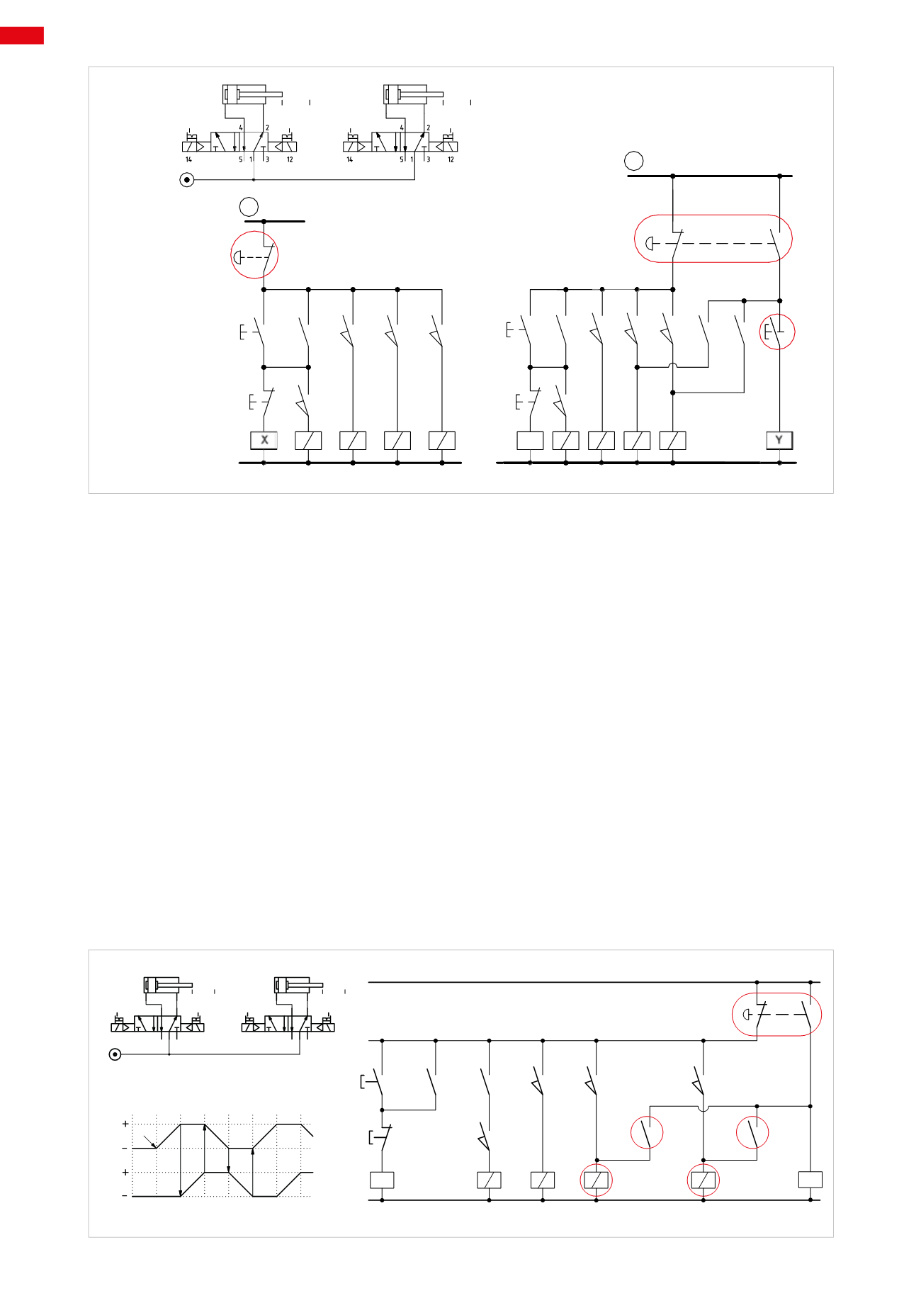
Fig. 20
Stop and re-positioning of the cylinders
As mentioned in the previous paragraph, the safety condition depends on the type of system used. In a pneumatic
press for example, the safety condition requirement is a free working area, normally achieved by exhausting the
compressed air supply from the rod lock. On a gripper or suction cup however, the compressed air supply must be
maintained so as to hold the component in its position.
Depending on how the EM command is connected, it is possible to manage the movement of the cylinders, e.g.
intervening even before they have reached the end position of their stroke.
Figure 21
The diagram below demonstrates two cylinders operated by their respective bistable 5/2-way solenoid valves.
To prevent the piston rod/pistons from reaching their end positions and reversing their stroke in the presence of the
EM command, it is necessary for the EM control to perform the following functions simultaneously:
• cut power from the control lines of the solenoid valves
• send the command to energize the solenoid valves - so they charge over and the actuators adopt their initial
positions.
The EM command, in addition to removing power from all the limit switches, permits the passage of the electric
signal to the coil of relay
Y
, energizing it, and thereby closing contacts
y
and
y1
.
With the closure of
y
and
y1
, solenoids
B2
and
B4
are energized. The solenoid valves reposition the piston rod/
piston by changing over. However, this solution may not be fully effective. In the absence of an electric current,
it will not be possible to change over the solenoid valves to reposition the cylinders which would complete their
current stroke and then stop. When using monostable solenoid valves, the outcome is different. The internal spring
in the valve causes the repositioning of the actuators if the electrical signal on the respective solenoids were to be
interrupted through the EM command or a cut in the electrical supply.
1 3
5
2
4
14
12
1 3
5
2
4
14
12
1
1
2
3
4
5
A
B
a0 a1
b0 b1
B1
B2 B3
B4
x
x
a1
b1
a0
I.C.
F.C.
EM
b0
y
y1
X
B 1
B 3
B 2
B 4
Y
NO/1-2
NO/4-5
A
B
1 2
1 2 3
3 4
a0
a1
b1
b0
I.C.
Fig. 21
6
208
CAMOZZI
>
ELECTRO-PNEUMATIC CIRCUITS