


 213 / 218

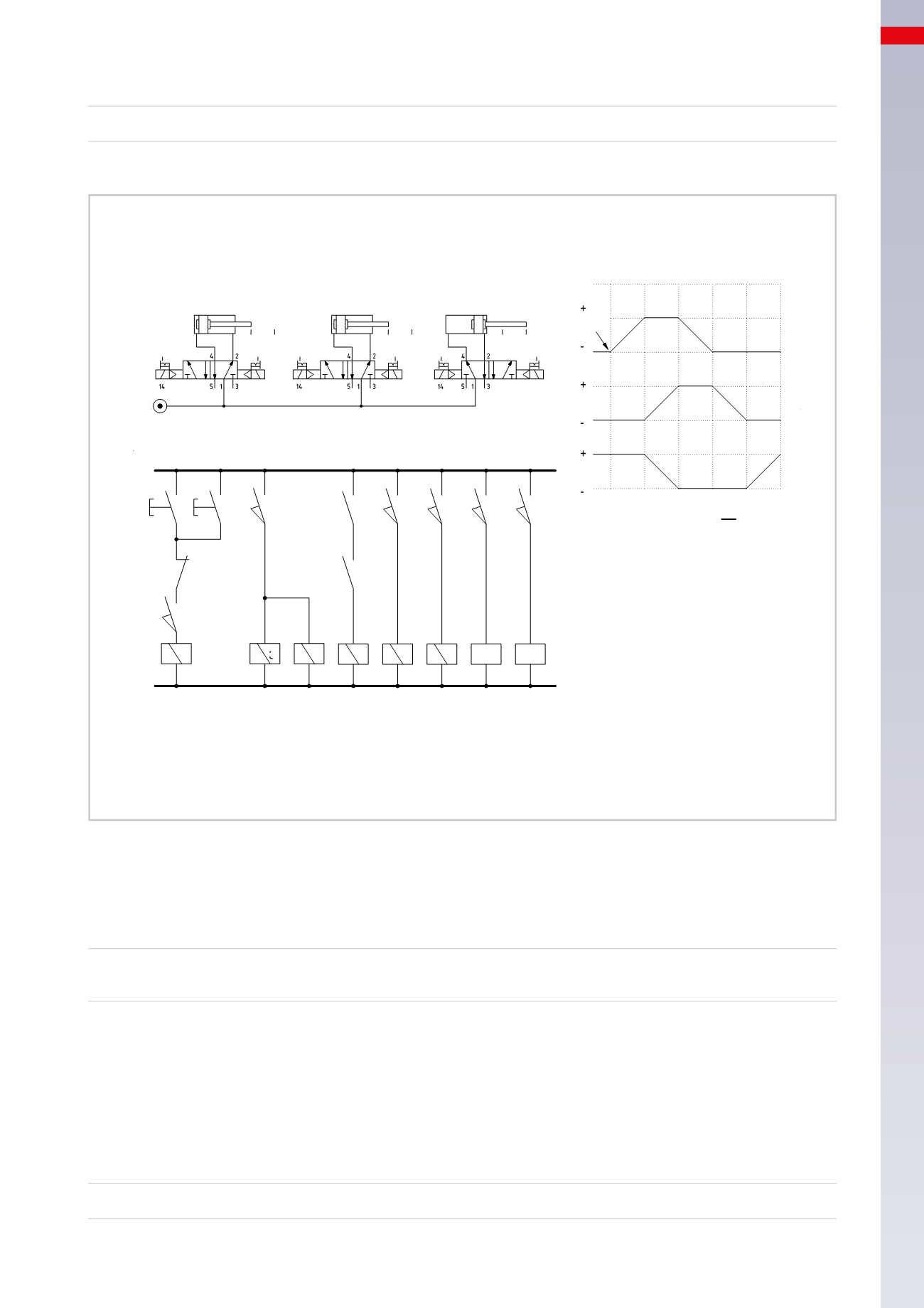
ELECTRO-PNEUMATIC CIRCUITS
The equation for this motion is:
b0 =
C +
When end position
c1
is reached, return to
Phase 1
and the cycle resumes.
NO/3-4
NC/1
c1
x
P1
P2
y a0
b0
b1
c0
NO/3-5
x1
a1
a0 a1
A
c0 c1
C
B2
B1
B5
B6
b0 b1
B
B4
B3
c0
b0
b1
a0
a1
I.C.
A
B
C
1 2 3 4
5
1
1
2
3
4
5
6
7
B 1
B 3 B 6 B 2 B 4 B 5 X
Y
(P1 + P2) * c1 + b1 = A +
a1
= B + C -
b1 * c0
= A -
a0
= B -
b0
= C +
c1
Fig. 23
We develop the previous sequence using the continuous cycle function and replacing the solenoid valve of cylinders
A
and
B
with monostable valves, while the solenoid valve of cylinder
C
remains bistable as it is activated for more
than one phase. The two buttons
P1
and
P2
are replaced by the
I.C.
button.
The cycle to be realised is:
A + / B +C – / A – / B – / C +
1
2
3
4
5
Figure 24
Phase 1:
stroke
A +
The safety condition required to carry out this stroke; the piston rod/piston of cylinder
C
must have completed the
positive stroke.
Line 1:
when the button
I.C.
is activated, as contact
c1
of the limit switch and the
F.C.
button are closed, the coil
of relay
X
energizes and, via contact
x
, the
I.C.
latches.
Line 2:
solenoid
B1
of the valve energizes, the valve changes over, the piston rod/piston of cylinder
A
completes
the positive stroke. The equation for this motion is:
I.C. * c1 =
A +
6
211
CAMOZZI
>
ELECTRO-PNEUMATIC CIRCUITS