


 207 / 218

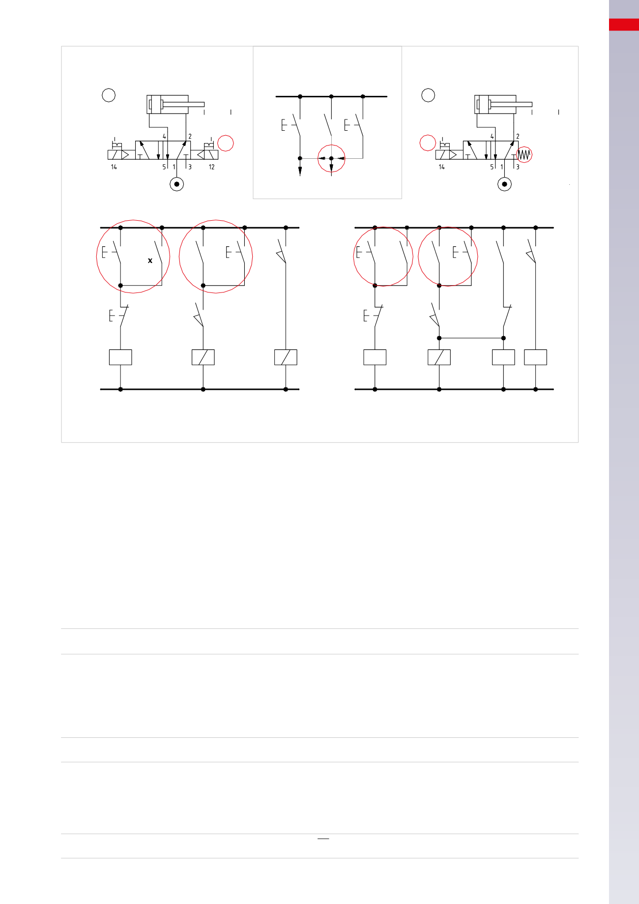
ELECTRO-PNEUMATIC CIRCUITS
1
2
B1
B2
A
a0 a1
C.C.
C.S.
1
1
2
x
B1
A
a0 a1
1
1
2
2
3
4
1
1
2
2
3
a1
a1
C.C.
F.C.
F.C.
C.S.
x
x
C.C.
x
a0
X
X
Y Z
B 1
B 1
B 2
NO/1-2
NO/1-2
NO/3 NC/3
C.S.
x
y
a0
z
Fig. 18
In this section we analyze two circuit solutions for the realization of a sequence with the continuous cycle
command (more commonly defined as Automatic Cycle, AUT) and the single cycle (more commonly defined as
manual, Man). As in the previous case, we use a single cylinder for convenience.
Figure 19
Pos. 1:
manual control for both strokes of the cylinder. The selector chooses the mode of operation i.e.
AUT.
or
Man.
mode.
AUT mode.
The buttons
Man A +
and
Man A –
are disabled.
To start the cycle, the operator must press the
I.C.
button, permitting the signal to reach the contact
F.C.
which
is closed in this phase. The signal passes through
F.C.
and energizes the coil of relay
X
. The contacts
x
and
x1
on
Lines 1
and
2
close.
X = AUT * I.C. * F.C.
Line 1:
with the closing of contact
x
the
I.C.
command latches.
Line 2:
with the contact
x1
closed, the signal reaches limit switch
a0
. In this state the contact is closed, as the
limit switch is activated by the presence of the piston rod/piston at the negative end position. The signal passes,
arriving at solenoid
B1
of the valve, which changes over to execute the positive stroke of the piston rod/piston of
the cylinder.
B1 = x1 * a0
Line 3:
once the positive end position has been reached, limit switch
a1
is activated and, by closing, allow the
signal to pass and energize solenoid
B2
.
As limit switch
a0
is no longer activated, solenoid
B1
is not energized. The now energized solenoid
B2
, changes the
solenoid valve over to execute the return stroke. When limit switch
a0
closes the cycle restarts.
B2 = a0 * a1
6
205
CAMOZZI
>
ELECTRO-PNEUMATIC CIRCUITS