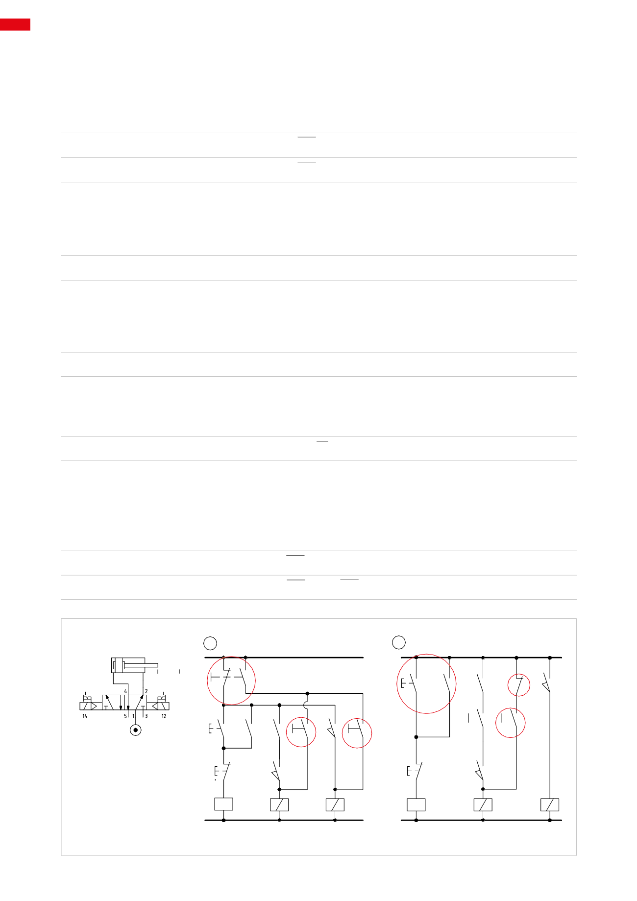

Figure 19
Manual Mode
The switch in this position will disable the entire circuit linked to the automatic mode, the only active remaining
buttons are
Man A +
and
Man A –
.
Their activation device is stable so as to avoid the movement of the cylinder in the event of an accidental activation
of the other device.
B1 = AUT * Man A +
B2 = AUT * Man A –
Pos. 2:
automatic return of the cylinder from the positive position during manual operation.
Line 1:
with the activation of the
AUT
button, the signal passes the contact of button
F.C.
(being
NC
) and energizes
the coil of relay
X
. The contact
x
closes, latching the AUT command.
Relay
X
has three contacts, two of which are
NO
(
x
and
x1
) and one
NC
(
x2
).
X = AUT * I.C.
Line 2:
contact
x1
is closing, permitting the electrical signal to reach the
I.C.
button, which once activated, allows
the signal to reach limit switch
a0
. In this phase the contact of
a0
is closed as it detects that the piston rod/piston
is located in this position, the signal passes, energizing solenoid
B1
. The solenoid valve changes over and the piston
rod/piston initiates the positive stroke.
B1 = x1 * I.C. * a0
Line 3:
upon arriving at limit switch
a1
the contact closes and the signal energizes solenoid
B2
. The solenoid valve
changes over and reverses the movement. This is possible as the piston rod/piston releases limit switch
a0
during the
positive stroke, interrupting the signal to solenoid
B1
.
B2 = a0 * a1
With the reversal in direction of movement of the cylinder,
a0
closes again and the cycle repeats.
The
F.C.
command interrupts the latching of AUT and the cycle stops, the contact
x2
returns in the closed position
and allows the activation of the selector
Man A +
. As long as this command remains active it maintains coil
B1
energized and the cylinder remains in the positive end position. With its removal, the signal on
Line 3
passes, and
energizes the solenoid
B2
reversing the movement of the piston rod/piston.
B1 = AUT * x2 * Man A +
B2 = AUT * x2 * Man A +
1
2
B1
B2
A
a0 a1
1
2
3
1
1
2
2
3
a1
a1
F.C.
I.C.
x1
x
a0
X
X
B 1
B 1
B 2
B 2
NO/1-2
NO/1-2 NC/2
a0
Man
AUT
AUT
Man
A+
Man
A-
Man
A+
F.C.
x1
x2
x
I.C.
Fig. 19
6
206
CAMOZZI
>
ELECTRO-PNEUMATIC CIRCUITS


