


 216 / 218

NO/6 NC/3-4
B
NO/1-2
NO/3 NC/6-7
X
F.C.
B 1
a0
x
I.C.
1
x1
2
Y
B
z
z1
B
3
4
y
a1
3
4
-
b1
5
I.C.
+
+
-
A
a1
b1
2
1
3
Z
B 2
y1
y2
z2
b0
6
b0
7
a0
4 1
1
a0 a1
A
b0 b1
B
B2
B1
B3
B4
Fig. 25
In this examplewe construct a circuit comprising three cylinders, the cycle is:
A+ / B+ / B – / C+ / C – / A –
1
2
3
4
5
6
Cylinder
A
: remains in a definite position (positive end position) during
Phases 2
,
3
,
4
and
5
here it is preferable
to use a bistable solenoid valve.
Cylinder
B
: is only active during
Phase 2
it is preferable to use amonostable solenoid valve.
Cylinder
C
: is only active during
Phase 4
, it is preferable to use amonostable solenoid valve.
Blocking signals generated by limit switches can be detected by observing the flow chart:
•
a1
: activated by the positive stroke of the cylinder
A
, it enables
Phase 2
for the positive stroke of cylinder
B
however obstructs the negative stroke during
Phase 3
.
•
b0
: activated by cylinder
B
in the rest position, it enables
Phase 4
for the positive stroke of cylinder
C
however
obstructs the negative stroke during
Phase 5
.
•
c0
: activated by cylinder
C
in the rest position, it enables
Phase 6
for the negative stroke of cylinder
A
however
obstructs the positive stroke during
Phase 1
.
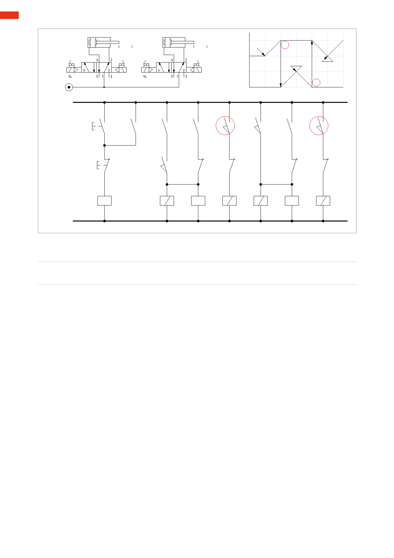
Figure 26
Phase 1:
stroke
A+
The safety condition required to execute this stroke; the piston rod/piston of cylinder
A
must have completed the
negative stroke.
Line 1:
with the activation of the
I.C.
button, the coil of relay
X
energizes and, via the closure of its contact
x
the
I.C.
latches.
Line 2:
contacts
x1
and
a0
are closed, solenoid
B1
energizes and the valve changes over, the piston rod/piston of
cylinder
A
executes the positive stroke.
Line 3:
in addition to solenoid
B1
, the coil of relay
Y
also energizes and latches due to the closure of its contact
y
.
The signal to solenoid
B1
remains active as long as the relay
Y
coil is energized.
Phase 2:
stroke
B+
Line 4:
contacts
a1
and
y1
are closed, the solenoid
B3
of the valve energizes, the valve changes over, the piston
rod/piston of cylinder
B
completes the positive stroke.
Phase 3:
stroke
B –
Line 5:
upon reaching limit switch
b1
, the coil of relay
Z
energizes, by closing its contact
z1
it latches, contact
z
opens simultaneously on
Line 3
, interrupting the latching of the relay
Y
coil.
Contact
y1
of
Line 4
opens and interrupts the energizing of solenoid
B3
, permitting the return of the piston rod/
piston of cylinder
B
.
6
214
CAMOZZI
>
ELECTRO-PNEUMATICCIRCUITS