


 211 / 218

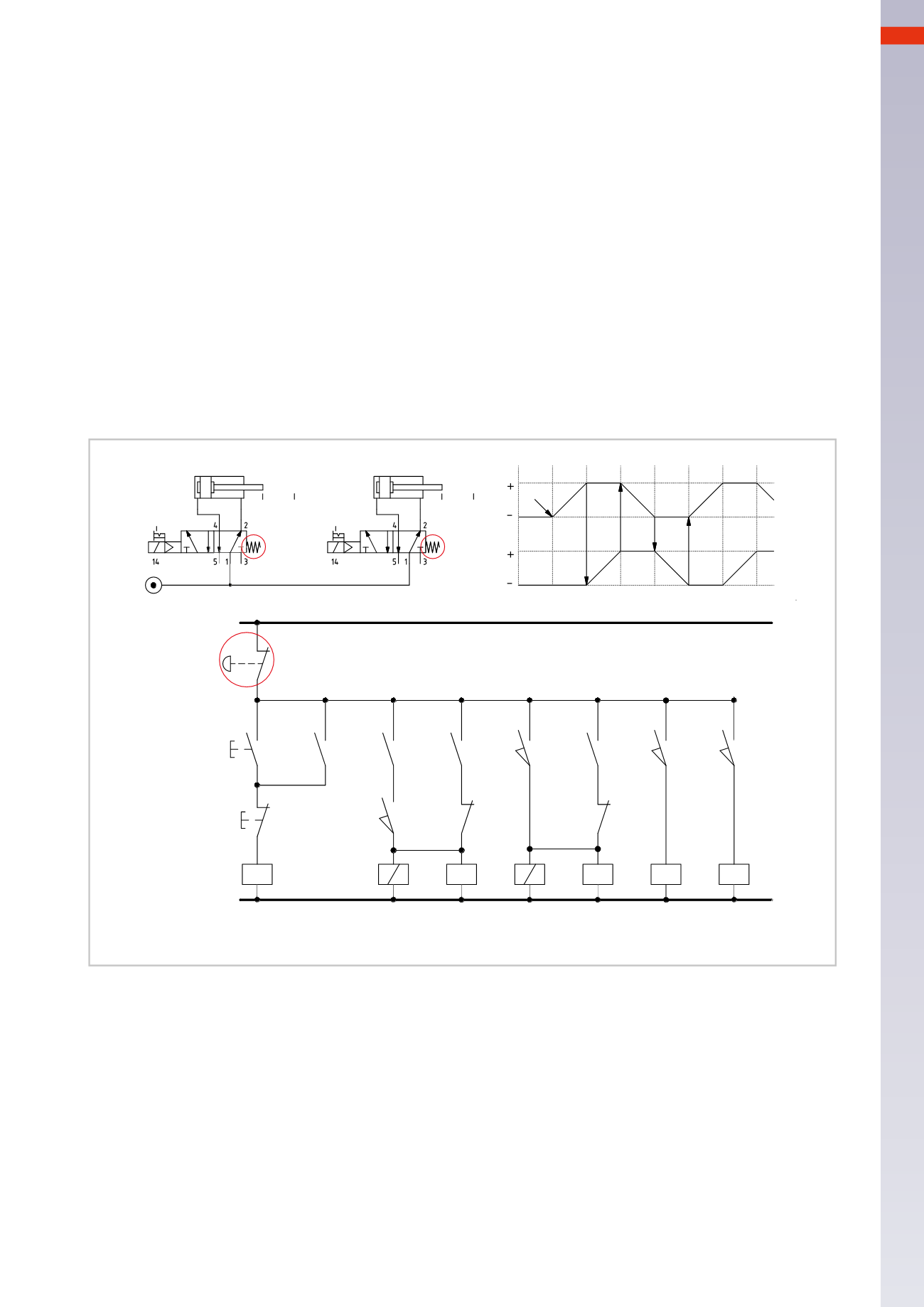
ELECTRO-PNEUMATIC CIRCUITS
Figure 22
Bistable solenoid valves are replacedwithmonostable solenoid valves. The circuit is simplified for theEM command,
but is complicatedwith regards to the development of the sequence under normal conditions.
Three latching circuits must be introduced in order tomaintain the electrical signal to charge over themonostable
solenoid valves. The sequence develops as previously. The latching on the various lines have the following functions:
Line 1:
contact
x
is latching the
I.C.
command.
Line 2
and
3:
contact
y
keeps the solenoid B1 energized, alsowhen contact
b0
is open.
By energizing solenoid
B1
the piston rod/piston of cylinder
A
completes the positive stroke releasing limit switch
a0
. In the absence of latching, the piston rod/pistonwould return to the starting positionwithout having completed
the stroke.
Line 4
and
5:
once position
a1
has been reached, the coil of relay
U
and the solenoid
B3
are energized.
By energizing solenoid
B3
the piston rod/piston of cylinder
B
completes the positive stroke, releasing limit switch
b0
.
Contact
u
maintains coil
B3
energized alsowhen contact
a1
is open.
With limit switch
b1
activated, the coil of the relay
Z
energizes, opening contact
z
and de-energizing solenoid
B1
.
Line 6:
upon reaching position
b1
, contact
z
on
Line 3
opens, solenoid
B1
is no longer energized; the piston rod/
piston of the cylinder
A
completes the negative stroke, releasing limit switch
a1
.
Line 7:
upon reaching position
a0
contact
v
on
Line 5
opens, solenoid
B3
is no longer energized; the piston rod/
piston of the cylinder
B
completes the negative stroke, releasing limit switch
b1
.
By activating theEM command the electric power to both the buttons and limit switches is cut. The solenoid valves
are no longer energized and therefore allow the repositioning of the piston rod/pistons of cylinders
A
and
B
.
A
B
a0 a1
b0 b1
B1
B3
A
B
1 2 3
1 2 3
4
a0
a1
b1
b0
I.C.
1
1
2
3
4
5
6
7
a0
b1
u
a1
y
x1
x
I.C.
EM
F.C.
b0
z
v
V
Z
U
3B
Y
X
1B
NO/3
NO/1-2
NO/5
NC/3
NC/5
Fig. 22
6
209
CAMOZZI
>
ELECTRO-PNEUMATICCIRCUITS