


 217 / 218

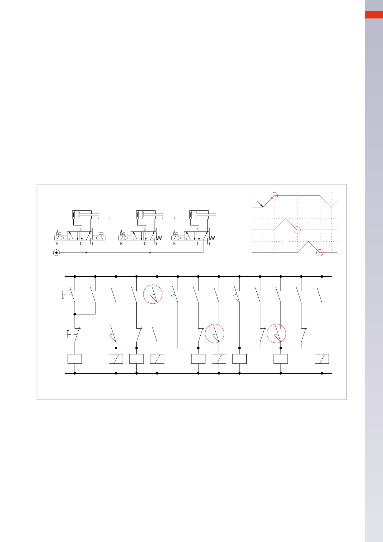
ELECTRO-PNEUMATIC CIRCUITS
Phase 4:
stroke
C+
Line 6:
upon reaching limit switch
b0
, with contact
z2
closed in this phase, solenoid
B5
of the valve energizes,
allowing the positive stroke of the piston rod/piston of cylinder
C
.
Phase 5:
stroke
C –
Line 7:
upon reaching limit switch
c1
, the coil of relay
K
energizes, closing its contact
k1
, and latches, contact
k
on
Line 5
opens simultaneously and interrupts the latching of the relay
Z
coil.
Contact
z2
on
Line 6
opens and interrupts the energizing of solenoid
B5
, permitting the negative stroke of the
piston rod/piston of cylinder
C
.
Phase 6:
stroke
A –
Line 8:
upon reaching limit switch
c0
, with contact
k2
closed, the coil of relay
M
energizes, it closes contact
m1
and latches.
Line 9:
at the same time contact
m2
closes, energizing solenoid
B2
of the valve, which by changing over allows
the piston rod/piston of cylinder
A
to complete the negative stroke.
At the end of the negative stroke, in the
a0
position, the cycle resumes providing the
F.C.
button has not been
pressed as contacts
x
and
x1
on
Lines 1
and
2
are closed.With the activation of limit switch
a0
, the relay
Y
coil is
re-energized, its contact
y2
on
Line 8
opens, interrupting the latching of relay
M
, contact
m2
opens and solenoid
B2
on
Line 9
is no longer energized.
Conversely, by pressing the
F.C.
button, the latching of relay
X
is interrupted thereby removing the power supply
to limit switch
a0
, the sequencewill continue until it reaches the end of the cycle and then stop.
B
-
+
+
A
- I.C.
1 2
4 5 6
C
-
+
3
a1
b0
c0
X
F.C.
x
I.C.
x1
a0
z
y
B 1 Y
a1
y1
B 3
b1
z1
k
Z B 5
b0
z2
c1
K
m
k1
M
c0
k2 m1
y2
m2
B 2
1
1
2
3
4
5
5
6
7
7
8
8
9
NC/1-2
NC/8
NO/3-4
NC/3
NO/5-6
NC/5
NO/7-8
NC/7
NO/8-9
c0
a1
C
B5
b0 b1
B
B2
B1
a0
A
B3
c1
Fig. 26
6
215
CAMOZZI
>
ELECTRO-PNEUMATICCIRCUITS