


 40 / 218

Compressors
With a bicycle pump it is possible to raise the air pressure from atmospheric to a higher value, i.e. it is possible to
compress and store the air within the bicycle tube to the pressure value necessary.
As discussed in the previous chapter on Physics, an increase in air pressure is a direct result of the reduction in
the available container volume or an increase in the number of air molecules per given space.
The pumps producing compressed air according to this principle are often of the
volumetric compressor type
.
They can be divided into two groups,
reciprocating
and
rotary
depending on the mechanism used to create a
progressive reduction in the volume of air drawn into the pump inlet.
In this sectionwemake a few brief observations on the fundamental characteristics of thesemachines.
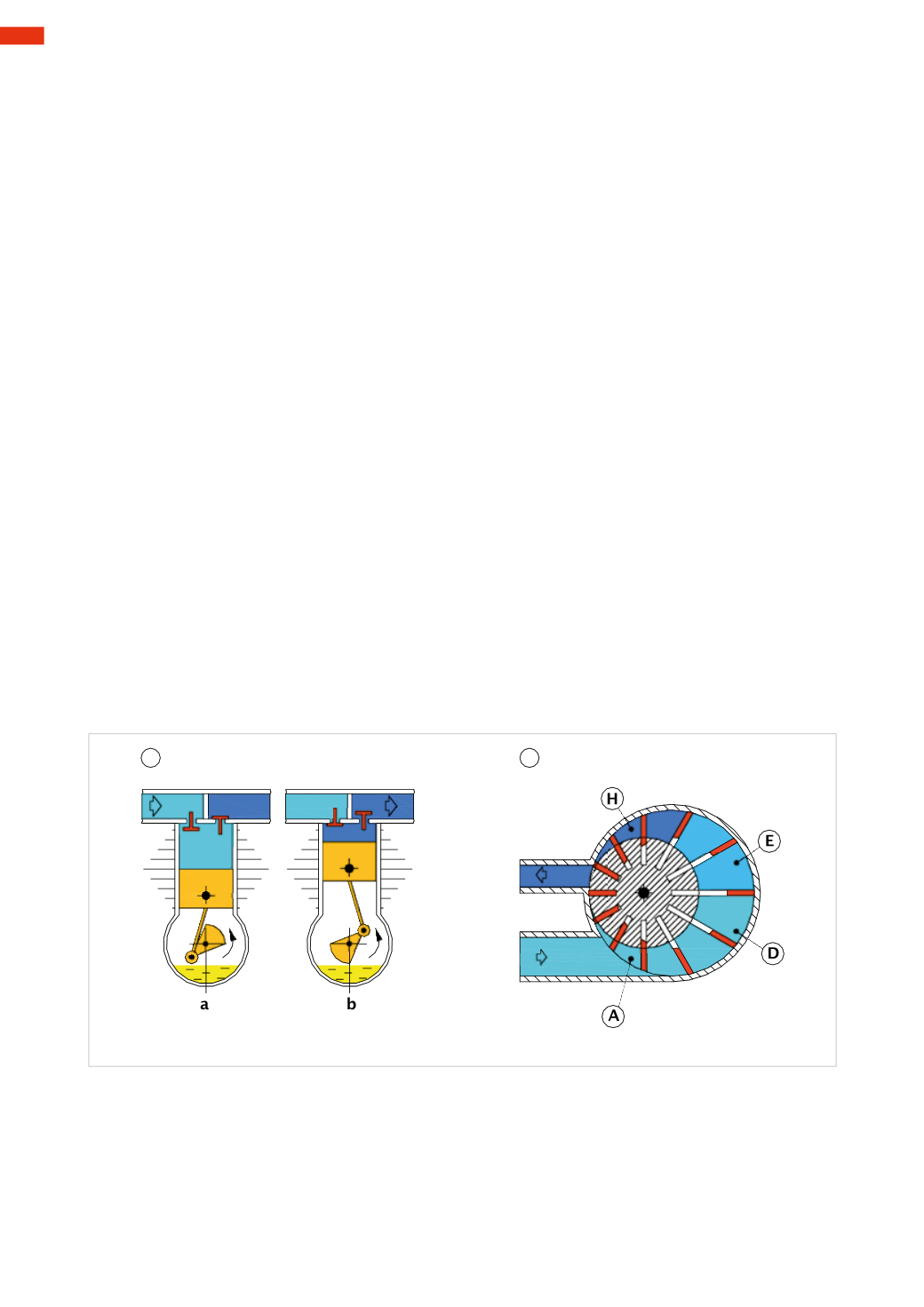
Figure 1
Pos. 1
:
Description and operation of a reciprocating compressor.
Themovement of the internal components is similar to that of a two-stroke petrol enginewith themajor difference
being that the compressor “crankshaft” requires an input from a power source such as an electricmotor.
a) as the piston descends it draws free air through the left inlet valvewhile the right remains closed.
b) as the piston is in the ascending phase, the left inlet valve closes, the right outlet valve opens when the pressure
created by the piston is sufficient for overcoming the resistance, the now compressed air is sent to the tankwhere
it is stored.
The external part of the sliding area of the piston is equipped with cooling fins to dissipate the temperature rise
generated by air compression and friction resulting from the sliding of the pistons.
At the same pressure and flow rate of air to be stored, the final temperaturemay be be contained in themain stage
by using
multistage compressors
. These use the following principle; air is drawn into the first stage chamber and
compressed to an intermediate pressure. Before the air is passed to the second compression stage it is cooled. The
cool air is then compressed further in the second stage thereupon reaching its final value.
Pos. 2
:
Operation of the rotary vane compressor.
This type of compressor is constructed from vanes,(blades)whichare free tomove radially, they are inserted in the
grooves cut into a cylindrical body (rotor). This body rotates inside a circular seat; the axis of rotation of the body
is moved laterally with respect to the theoretical axis of the circular seat, in this way a space is formed in which
the bladesmay create sectors inwhich there is air.
When the rotor rotates bymeans of a power source, the blades are forced outward by centrifugal force and the air
inlet is situated at the point where the volume between one blade and another is increasing. The outlet is situated
where the volume is decreasing.
The suction or inlet phase occurs at point
A
and the volume increases until the blades reach point
D
. From point
E
to point
H
the volume is progressively reduced. Unlike the reciprocating compressor, the production of compressed
air does not have alternating phases but is in continuous flow.
Cooling of the air can be achieved by the injection of oil, whichmust then be recovered, cooled and recycled.
1
2
Fig. 1
Figure 2
Operation of the rotary screw compressors.
These units are formed by twoworm screws positioned so that their surfaces are
almost
contacting.
a) The simplified front view shows the two screws with different profiles. The air is drawn in by the rotation of the
two screws.
b) With the rotation of the two screws the air is drawn in, the space available for the air is then reduced thus
initiating the compression phase and subsequent transmission to the outlet. This action occurs at every turn and
every “corner” of the left screw.
2
38
CAMOZZI
>
AIRPRODUCTIONANDPREPARATION