


 96 / 218

2
3
1
REST
POSITION
A
B
2
3
1
INTERMEDIATE
POSITION
A
B
2
3
1
OPERATED
POSITION
A
B
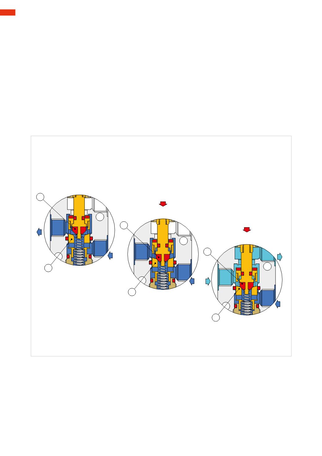
Fig. 6
The function of a 3/2-way NO poppet valve
As with the 3/2-way NC valve presented on the previous page, we observe the operation of a 3/2-way NO poppet
valve in the illustration below.
Figure 6
Rest position.
Pos. 1:
in this position, there is a passage from inlet 1 to outlet 2 due to the thrust of the small cylindrical spring
acting on the plunger
A
. The cartridge
B
, due to the effect of the seal
C
and the spring with a greater diameter,
simultaneously closes thepassage towards theexhaust 3. The compressedair is free to flow from inlet 1 tooutlet 2.
Intermediate position.
Pos. 2:
in this phase, the valve has not yet reached the final position: the plunger
A
is depressed and the seal has
closed the passage between inlet 1 and outlet 2 through contact with the plunger
B
, and exhaust 3 is still closed.
This intermediate stage is called “closed center” as all ports are isolated from each other.
Activated position.
Pos. 3:
in this position, the activation is complete: cartridge
A
and plunger
B
of the poppet have continued their
movement until the complete opening of the passage from outlet 2 to exhaust 3. The valve is kept in this state as
long as an external force depresses the plunger
B
.
Return to rest position.
When the actuation force on the plunger
B
is released, the cylindrical springwith a larger diameter raises both the
plunger and cartridge
A
, this is the “closed centers” state.
The smaller spring then raises the plunger
A
opening the passage between the inlet 1 and outlet 2. The plunger
B
,
due to the seal
C
, closes the passage to the exhaust 3. The valve returns to rest position.
Also with this type of poppet design, air supply is only possible from port 1, this feature is illustrated by the
pneumatic symbol that identifies a defined direction for the passage of the compressed air.
4
94
CAMOZZI
>
VALVES