


 94 / 218

1
2
3
1
2
3
1
3
5
2
4
1
2
3
NC
NO
3
1
12
10
2
3
1
2
A
C
B
D
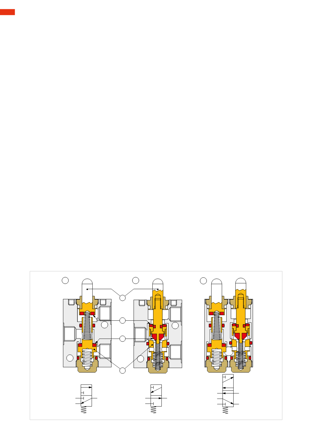
Fig. 4
Poppet valves
The design principle of pneumatic valves is not a function of the number of ways or the number of positions, but
depends on parameters such as the area of use, the flow rate, the size etc.
The number of waysmay be: 2, 3, 4, 5.
The positionsmay be: 2 or 3; there are valves with a higher number positions but they have a very limited use.
The different traditional types are:
poppet valves, spool valves, diaphragm valves, disc valves
.
Some valves are better adapted to a specific function; for example, diaphragm valves with a 2/2-way function are
more frequently observed than 5/2-way.
The valvesmay be defined as:
Normally Open (NO) or Normally Closed (NC)
NC or NO indicates whether or not there is passage of compressed air from inlet 1 to outlet 2 of the valve in the
rest position. The poppet and spool valves are those usedmost frequently in the pneumatic circuit from the valves
indicated above.
Figure 4
Pos. 1: 3/2-way valveNC.
The poppet is the component indicated by the letter
B
. Its rest position is given by the mechanical spring below
the poppet, by pushing it upwards allows for the seal (coloured in red) to seal, i.e. prevents the passage of the
compressed air from inlet 1 to outlet 2. Theupper poppet encloses a springwhich separates the part
B
from
A
, this
arrangement allows outlet 2 to be in communicationwith exhaust 3.
The valve is activated by pushing the pin
A
downwards: during its movement while coming into contact with
B
,
it closes the exhaust 3, then, by compressing the spring below the poppet
B
, opens the passage between the inlet
1 and outlet 2.
Removing the activation force from the pin
A
, the springs re-assume their initial size returning the valve to its
normal (non-activated) closed position.
Pos. 2: 3/2-way valveNO.
Here the function is inverted compared to the normally closed valve.
At rest position, the seal
D
is not in contact with the poppet
B
, the compressed air at the inlet 1 is free tomove
towards the outlet 2 and the seal
C
blocks the exhaust port 3.
The valve is activated by pushing the pin
A
downwards: during itsmovement, the seal
D
comes into contact with
the poppet
B
closing the passage from the inlet 1 to outlet 2, with the lowering of poppet
B
the seal
C
detaches
itself from the seal on the valve body, opening the passage of exhaust air from the outlet 2 to the exhaust 3.
The poppet valves, and in particular those which aremechanically controlled, include an extra stroke that allows
for a safety margin to avoid the peak load that could damage the valve, this in addition to the stroke required to
open/close the valve. By not completing the full stroke of the pin
A
, there is a reduction of flow.
On the pneumatics symbol, the location of the numbers, (and in this case also the return spring), are indicated on
the square that identifies the rest position of the valve.
Pos. 3: 5/2-way valve.
This valve is constructed by placing the internal components of the 3/2-way
NC
and 3/2-way
NO
valves side by
side in one body, channelling the inputs into a single connection. In 5/2-way valves NC or NO versions do not exist
because the input 1 is always open in communicationwith one of the two outlets 2 or 4.
4
92
CAMOZZI
>
VALVES