


 98 / 218

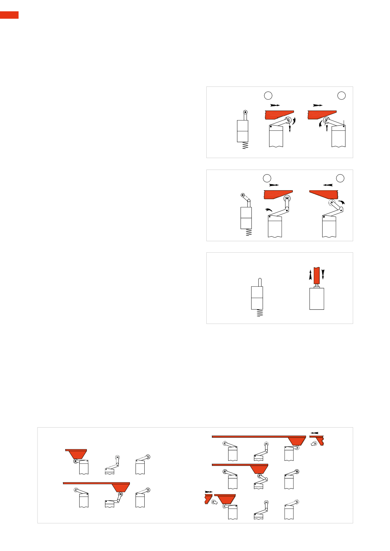
Figure 10
Pos. 1
and
2: roller lever, monostable operation,
spring return.
The drive requires a continuous pressure on the roller
lever and allows the passage of the compressed air if
the valve isNC or its interruption if NO. Such passage
continues for as long as the drive continues.
The roller lever control is used when the object in
motion (cam), which drives the mechanical device
of the limit switch, has a direction of movement
perpendicular to the valve axis. For correct assembly,
the limit switchmust be oriented so that the rotation
of the lever is in the same direction as themovement
of the cam. The return of the valve is set using an
internal spring.
Figure 11
Pos.1
and
2: one-way roller lever control,monostable
operation, spring return.
Corresponds to the roller lever, but the particular
conformation of the drivemakes it unidirectional, the
switching only occurs in one of two directions.
Figure 12
Front control, monostable operation, spring return.
This type of command is used when the object in
motion, which activates themechanical device of the
limit switch, ismoving parallel to the axis of the valve.
At the end of themovement, itmust be ensured that
theobject inmotiondoesnot activate the front control
above themaximum allowed value, given by the sum
of the stroke and the extra-stroke.
ROLLER
OPERATION
LEVER
COMMAND
A
NO!
1
2
Fig. 10
ONE-WAY
OPERATION
ROLLERLEVER
COMMAND
1
2
Fig. 11
FRONT
OPERATION
COMMAND
Fig. 12
Examples of activation
:
Figure 13
A:
with the object in motion (cam) having returned in the starting position, only the first limit switch remains
activated, the others are at rest.
B
: with the cam in the intermediate position, it reaches the limit switch with amechanical device operated by a
unidirectional roller lever and activates it for the entire length of the cam.
This limit switch is at a lower position because themechanical control device of aunidirectional lever roller is larger.
C:
with the cam in the end position, it activates the last limit switchmounted in the direction opposite to the first
cam and keeps it in operation.
D:
during the return stroke, the cam,which is inan intermediateposition, lowers theonly part of the lever inwhich
the limit switch has a one-way function (the knee), thus avoiding switching.
E:
with the cam having returned to the starting position, it only keeps the first limit switch activated.
Mechanical operation of poppet valves
In an automated system human intervention is limited to the start-up or to resolve any emergencies. The progress
of the sequence is determined and controlled by “switch” valves that release a signal when activated. Their
operation - in this case “mechanical”, is determinedby attainment of thedesiredpositions by the bodies inmotion,
for example cylinders.
Some types of mechanical control.
SIMULATIONOFCOMMANDSWITHROLLERDEVICES
A
B
C
D
E
NO!
NO!
Fig. 13
4
96
CAMOZZI
>
VALVES