


 95 / 218

VALVES
2
3
1
A
B
2
3
1
INTERMEDIATE
POSITION
A
B
2
3
1
OPERATED
POSITION
A
B
REST
POSITION
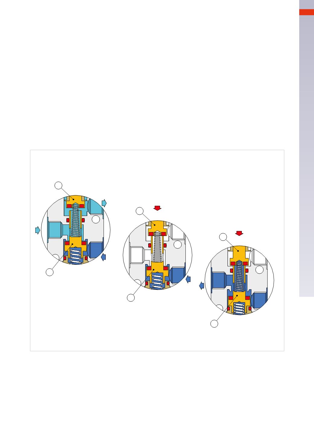
Fig. 5
The function of a 3/2-way NC poppet valve
The illustration below demonstrates the internal workings of a 3/2-wayNC valve during the three different phases
of aworking cycle: rest, intermediate, and activated.
Figure 5
Rest position.
Pos. 1:
in this phase, there is passage between the outlet port 2 and exhaust port 3 due to the thrust of the spring
positioned between the actuation pin
A
and plunger
B
. Through this action, the compressed air coming from outlet
2, is discharged through exhaust 3. The plunger
B
ismaintained in position through the thrust of the lower spring
that closes the passage of air coming from inlet 1.
Intermediate position.
Pos. 2:
in this phase, the valve has not yet reached the final position: the actuation pin
A
is lowered, and by
coming into contact with the plunger
B
, closes exhaust 3. In this phase the plunger
B
has not yet reached its end
position so there is not yet a passage of air from inlet 1 to the outlet 2. This intermediate stage is referred to as
“closed center” as all ports are isolated from each other.
Activated position.
Pos. 3:
in this position, the stroke of the actuation pin
A
and plunger
B
is complete: the actuation pin
A
has not
only closed the passage as previously observed, but also pushed down the plunger
B
towards its end position thus
opening the passage between inlet 1 and the outlet 2. The valve is maintained in this state for as long as the
actuation pin
A
is depressed by the action of an external force.
Return to rest position.
When the actuation force is removed from the actuation pin, the spring positionedbelow the plunger
B
, raises both
the plunger
B
and actuation pin
A
, inlet 1 is closed, andwe return back to the “closed centers” phase.
Subsequently, the spring between the actuation pin
A
and plunger
B
, raises the actuation pin
A
and opens the
passage between the outlet 2 and exhaust 3 so compressed air exhausts into the atmosphere. The valve is then
returned to the rest position.
With this type of plunger, the incoming compressed air can only enter through inlet 1; this feature is illustrated by
the pneumatic symbol that identifies one direction only for the flow of the compressed air.
A possible air supply via the connections 2 or 3would not assume the function of NO, in fact the plunger
B
would
be pushed down by the air pressure, also opening the passage through port 1.
4
93
CAMOZZI
>
VALVES