


 99 / 218

VALVES
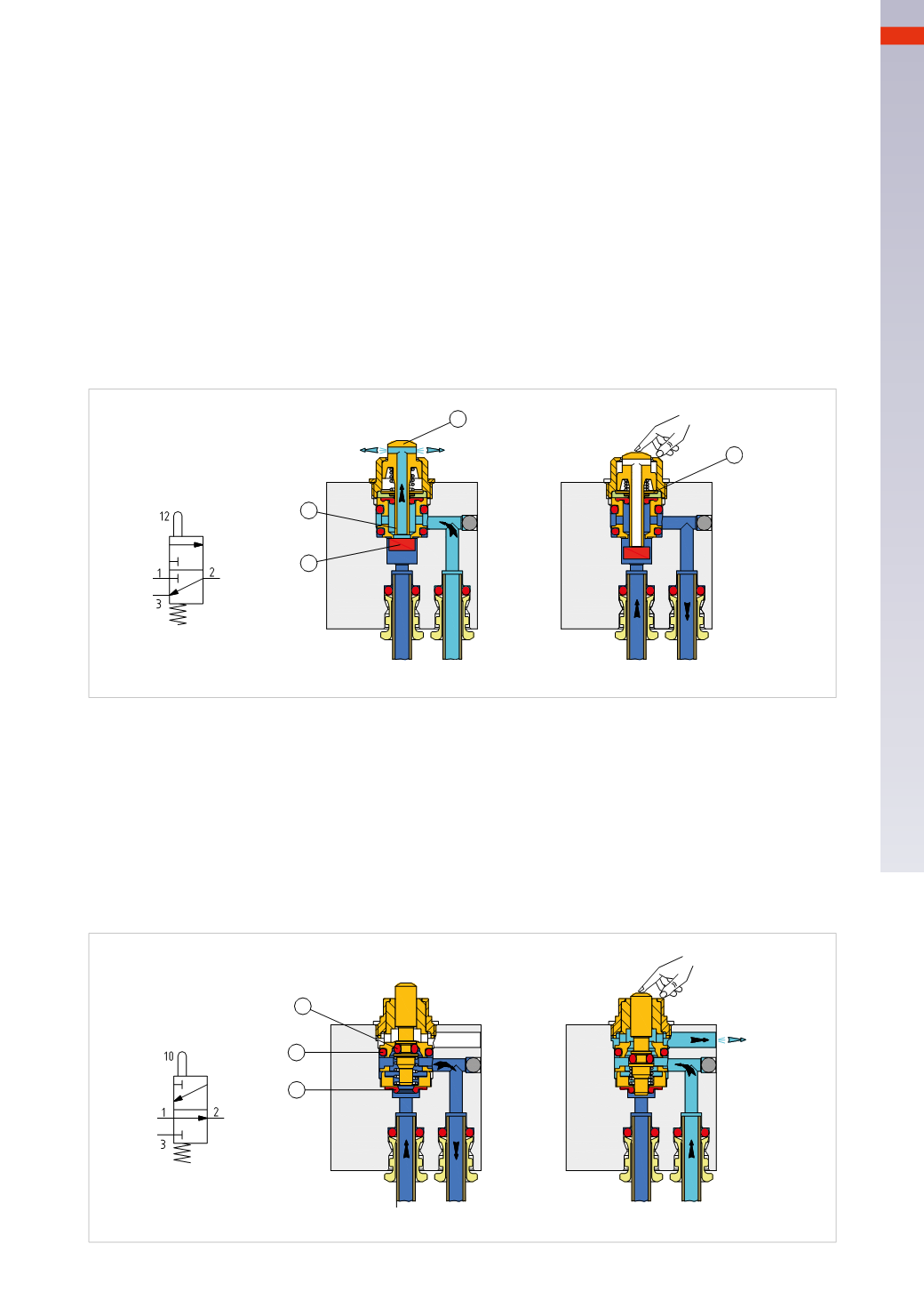
Figure 15
Model: 3/2-way NO
The connections for inlet 1 and outlet 2 are positioned exactly as they are on the NC valve, the exhaust port 3 is
located on the valve body and obtained through a side passagewhich is not threaded.
The compressed air from inlet 1 passes through the diaphragm
G
and the elevated plunger stem is able to go
towards outlet 2. The seal
E
closes the passage to the exhaust 3.
The activation of the mini-valve is obtained by lowering the plunger stemwith a small stroke. The passage from
inlet 1 to outlet 2 closes through the membrane
G
, and, at the same time, the seal
E
, through its movement,
opens the passage from the outlet 2 to the exhaust 3. Upon the release of the plunger stem, the internal spring
re-assumes the initial position and through seal
E
, closes the passage from outlet 2 to exhaust 3. The diaphragm
G
, upon release, reopens the passage from inlet 1 to outlet 2.
Mini poppet valves
In these types ofmini-valves, inorder to limit the size, not all of the connections have threadedports or aredesigned
for the insertion of the tube. It is also possible that both the threads and tube connection cartridges typically have
M5 dimensions (for threads) and cartridges for a 4
mm
tube diameter.
Figure 14
Model: 3/2-way NC
The tube connections to the inlet 1 and outlet 2 are located in the body of the valve. The exhaust port 3 is obtained
by the passage
B
located in the plunger stem “
A
”.
The compressed air from inlet 1 acts on the seal “
C
” which, by elevating, closes the passage through the plunger
stem
A
. Theoutlet 2and theexhaust port 3are in communication through thepassage
B
inside theplunger stem
A
.
The drive of the mini-valves is achieved by lowering the plunger stem
A
with a short stroke. The end part of the
plunger (whichacts as a shutter) bypushing the seal
C
, closes theexhaust 3 through thepassage
B
, andallows the
opening of inlet 1 towards the outlet 2. The ring “
D
” determines the value of themaximum stroke of the plunger.
As the activation of the plunger ceases, the air pressure in inlet 1 pushes the seal
C
upwards, at the same time as
the plunger stem
A
. Inlet 1 is closed and the internal spring pushes the stem further upwards, so that by detaching
itself from the seal, it reopens the passage between outlet 2 and exhaust port 3.
A
B
C
1
2
1
2
3
12
12
3
D
Fig. 14
F
G
1
2
1
2
3
10
10
3
E
Fig. 15
4
97
CAMOZZI
>
VALVES