
62
The company reserves the right to vary models and dimensions without notice.
These products are designed for industrial applications and are not suitable for sale to the general public.
FITTINGS BSP
Fittings BSP
2
NORTH AMERICAN FITTINGS & FLOW CONTROL VALVE CATALOG
>
Release 8.6
Fittings Mod. 6750
Tube Plug
DIMENSIONS (in mm)
Mod.
A
G
L
Weight (g)
6750 4
4
8.8
15
4
6750 6
6
11.8
17
7
6750 8
8
13.8
18.5
9
6750 10
10
15.8
21
12
6750 12
12
17.8
20
15
Fittings Mod. 6950
Double Stem Union
DIMENSIONS (in mm)
Mod.
G
L
Weight (g)
6950 4
4
32.5
3
6950 6
6
35.5
4
6950 8
8
40.5
7
6950 10
10
46
10
6950 12
12
48
13
6950 14
14
52
17
Fittings Mod. 6700
Cartridge
DIMENSIONS (in mm)
Mod.
A B D DE F G H H2 L S* P min (Kg) P max (Kg) Weight (g)
6700 4 4 3.5 8.8 14 8.6 9 11 3.3 14.5 8.75 200
360
4
6700 5 5 3.5 9.8 15 9.6 10 11.5 3.3 15.5 9.75 200
360
5
6700 6 6 4 12 17 11.8 12.2 12 3.8 16.5 11.95 160
570
8
6700 8 8 6 14 19 13.8 14.2 14 3.3 18 13.95 140
400
11
6700 10 10 8 16 21 15.8 16.2 16.5 3.5 20.5 15.95 150
650
15
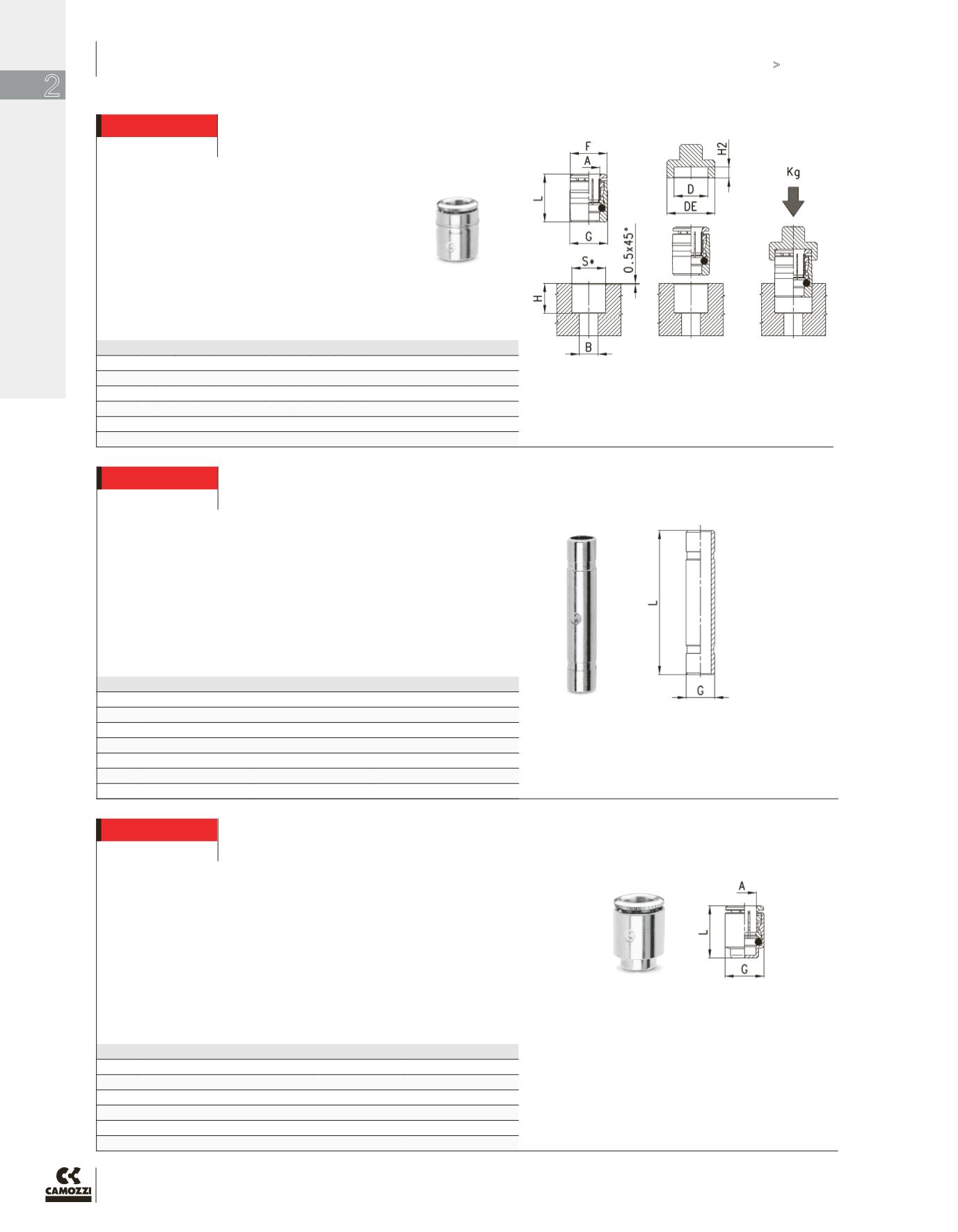
*S = metallic (+0.01, -0.04)
The Dimension ‘H2’ for the press-tool should be noted and followed,
which creates a specific mechanical stop. This serves the purpose of
avoiding, (in case of any excessive insertion force used), damage to the
collet body, shape or design. Without which, could lead to some damage
or distortion of the collet bite/release ring.
All Dimensions in millimeters. Surface Finish of the gland seat required:
Ra </= 0.8 microns.
Final Fit and Finish requires that the top most ridge/bite-ring of the
cartridge body be at least 1 mm below the surface of the gland chamfer.
For plastic (non-metal) manifolds, reduce all hole dimensions “S” by 0.02
mm (0.001 in.)


