


 50 / 226

Operating pressure
4-10 bar (58-145 psi)
Nominal pressure
6 bar, (87 psi)
Nominal flow
*Qn Series 3: 1/8” = 700 Nl/min. (24.7 SCFM) Cv ratin1/8 NPTF” = .73
Nominal diameter
1/8” = 5 mm
Fluid
Filtered air
Valve group
3-way/2-position, 5-way/2-position
Construction
Spool-type (servocontrolled)
Mounting
Mounting holes in valve body
Materials
Anodized body, stainless steel spool, Buna-N seals
Threaded port sizes
1/8” NPTF
Installation
In any position
Operating temperature
32° F - 175° F, (dry air necessary down to _4° F)
Fluid
Filtered air (25 micron or less recommended)
Lubricant
Not required; otherwise, oil compatible with Buna-N, (3° - 10° E) ( ISOVG 32 grade; 32 centistrokes)
The company reserves the right to vary models and dimensions without notice.
These products are designed for industrial applications and are not suitable for sale to the general public.
40
m e c h a n i c a l v a l v e s
2
Dimensions in millimeters (mm)
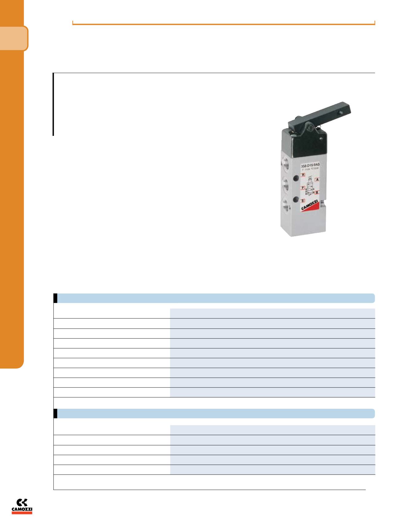
Series 3
Cv = .73
1/8” Ported Mechanically Operated Sensor Valves
(Whisker Valve)
3-way/2-pos i tion and 5-way/2-position
Ports 1/8” NPTF
In order to facilitate the use of limit switch valves in applications where
very lowactuating forces and high flowrates are required, the Series 3
valves are equipped with new mechanical devices designed for this pur-
pose. The Series 3 valve is designed with a mechanical lever which when
operated releases an internal pilot signal to atmosphere. Actuation forces
are less than 50g (2N); (.5 lbf) and the sensitivity can be increased by
adding a “whisker” or rod of dia. 3mm to the lever (cross-thread of M5 x
.8 can be used to hold “whisker-rod” in place)
The functions available are as follows:
for the 3 Series:
- 3-way/2-position normally closed or normally open (spring return)
- 5-way/2-position (spring return)
* These valves have an internal mechanical spring return and a pilot-
pressure spool plunger that shifts upon actuation of the lever by depres-
surizing the spool plunger. Valve symbols shown are “at rest” next to the
actuator symbol.
PNEUMATIC DATA
TECHNICAL SPECIFICATIONS
* Qn = determined with supply pressure of 6 bar and with Dp = 1 bar
**Dime io s are in millimeters
Cv = .73