
General terms and conditions for sale are available on
www.camozzi.com.2
Series P solenoid valves
CONTROL >
C_FLUID CONTROL CATALOGUE
>
2018
45
CONTROL
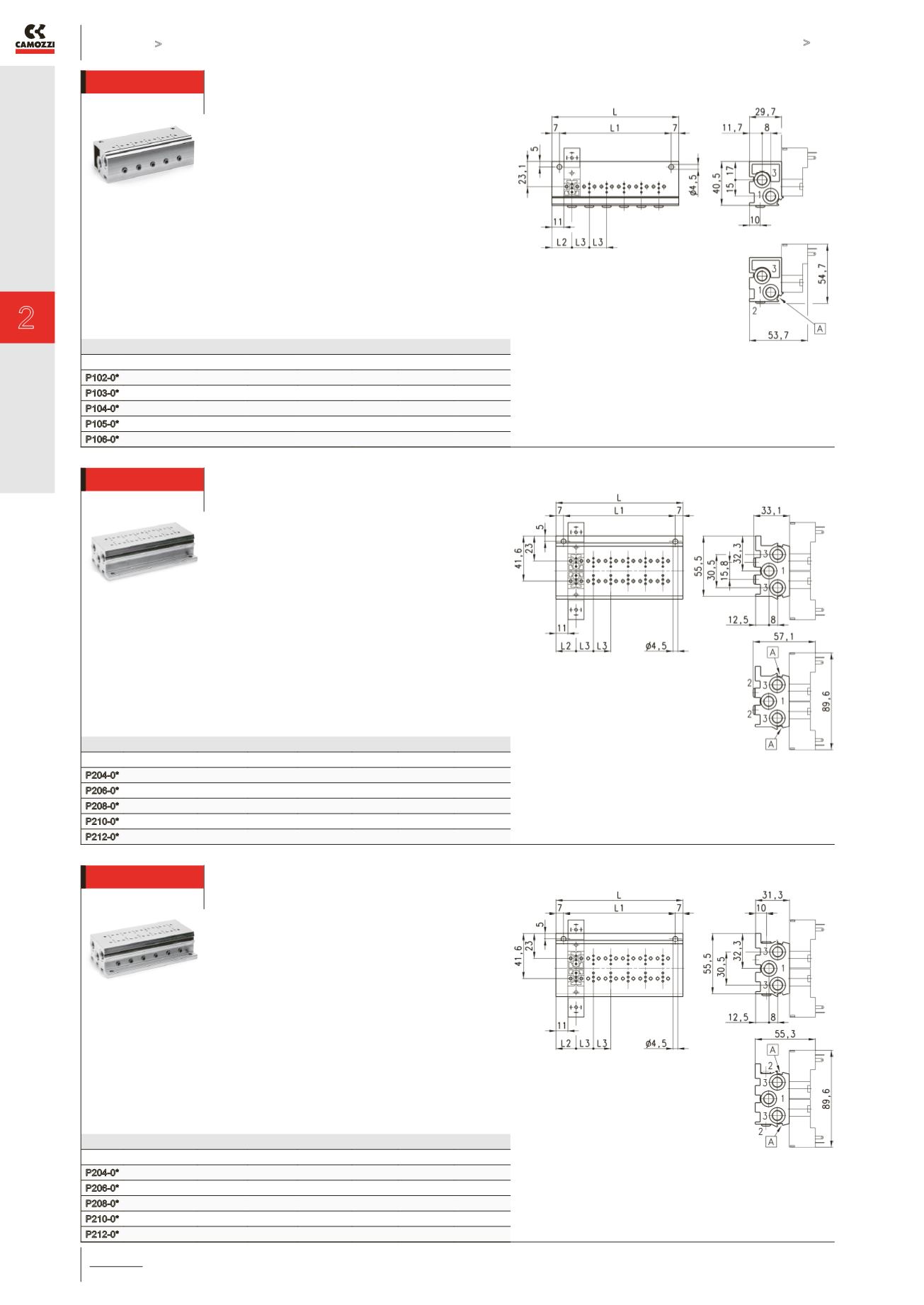
Single manifold with front outlets
This manifold is arranged to be fixed through
DIN 46277/3 guide together with the accessory
PCF-E520.
DIMENSIONS
Mod.
Nr valves
L
L1
L2
L3
1 (P)
3 (R)
P102-0*
2
53
39
18,5
16
G1/8
G1/8
P103-0*
3
69
55
18,5
16
G1/8
G1/8
P104-0*
4
85
71
18,5
16
G1/8
G1/8
P105-0*
5
101
87
18,5
16
G1/8
G1/8
P106-0*
6
117
103
18,5
16
G1/8
G1/8
* = see the type of PORTS in the
CODING EXAMPLE TABLE.
A = groove for electric connection
identification
Double sided manifold with rear outlets
DIMENSIONS
Mod.
Nr valves
L
L1
L2
L3
1 (P)
3 (R)
P204-0*
4
53
39
18,5
16
G1/8
G1/8
P206-0*
6
69
55
18,5
16
G1/8
G1/8
P208-0*
8
85
71
18,5
16
G1/8
G1/8
P210-0*
10
101
87
18,5
16
G1/8
G1/8
P212-0*
12
117
103
18,5
16
G1/8
G1/8
* = see the type of PORTS in the
CODING EXAMPLE TABLE.
A = groove for electric connection
identification
Double sided manifold with front outlets
This manifold is arranged to be fixed through
DIN 46277/3 guide together with the accessory
PCF-E520.
DIMENSIONS
Mod.
Nr valves
L
LI
L2
L3
1 (P)
3 (R)
P204-0*
4
53
39
18,5
16
G1/8
G1/8
P206-0*
6
69
55
18,5
16
G1/8
G1/8
P208-0*
8
85
71
18,5
16
G1/8
G1/8
P210-0*
10
101
87
18,5
16
G1/8
G1/8
P212-0*
12
117
103
18,5
16
G1/8
G1/8
* = see the type of PORTS in the
CODING EXAMPLE TABLE.
A = groove for electric connection
identification


