
General terms and conditions for sale are available on
www.camozzi.com.2
Series P solenoid valves
CONTROL >
C_FLUID CONTROL CATALOGUE
>
2018
43
CONTROL
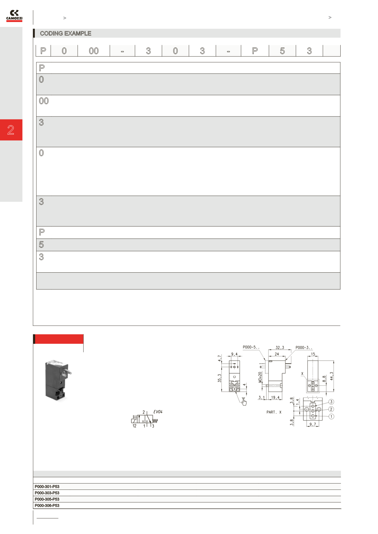
CODING EXAMPLE
P
SERIES
0
BODY DESIGN:
0 = single sub-base (M5 only) or interface
1 = single manifold
2 = double sided manifold
00
NUMBER OF POSITIONS:
00 = interface
01 = single base (M5 only)
02 ÷ 99 = manifold number of positions
3
NUMBER OF WAYS - FUNCTIONS:
0 = manifold or single base
3 = 3-way NC
4 = 3-way NO
5 = 3-way NC electric part revolved by 180°
6 = 3-way NO electric part revolved by 180°
0
VALVE PORTS:
0 = interface (for single valve only)
MANIFOLD PORTS (for Series W, P and PN):
2 = M5 side port
3 = ø 3 tube side port
4 = ø 4 tube side port
6 = M5 rear ports
7 = ø 3 tube rear ports
8 = ø 4 tube rear ports
3
NOMINAL DIAMETER - MAX PRESSURE
1 = ø 0,8 (1W) 10 bar (NC) 24V only
3 = ø 1,5 (2W) 7 bar (NC) 5 bar (NO)
5 = ø 1,1 NC (2W) 10 bar (NC)
ø 0,9 NO (2W) 10 bar (NO)
6 = ø 1,5 NC (2W) 3 bar (NC) *
P
MATERIALS:
P = technopolymer PBT body, FKM poppet seal, other seals in NBR (FKM on demand)
5
ELECTRICAL CONNECTION:
5 = industrial standard connection (9.4 mm)
3
SOLENOID VOLTAGE:
B = 24V 50/60 Hz 2 = 12V DC 6 = 110V DC
C = 48V 50/60 Hz 3 = 24V DC
D = 110V 50/60 Hz 4 = 48V DC
FIXING:
= with screws for metal (standard)
P = with screws for plastics
* Voltage tolerance from +10% to -25%
P 0 00 -
3 0 3 -
P 5 3
Mod.
Orifice Ø (mm)
kv (l/min)
Qn (Nl/min)
Pressure min-max (bar)
P000-301-P53
0,8
0.21
14
0 ÷ 10
P000-303-P53
1,5
0.54
35
0 ÷ 7
P000-305-P53
1,1
0.39
25
0 ÷ 10
P000-306-P53
1,5
0.54
-
0 ÷ 3
3/2-way NC solenoid valve
Supplied with:
1x interface seal
2x screws M3x20 UNI 8112
(fixing for metal, standard)
or
2x screws M3x23 UNI 10227
(fixing for plastics, P option)


