


 101 / 218

VALVES
3
1
5
4
2
14
12
5
3
1
2
4
A
B
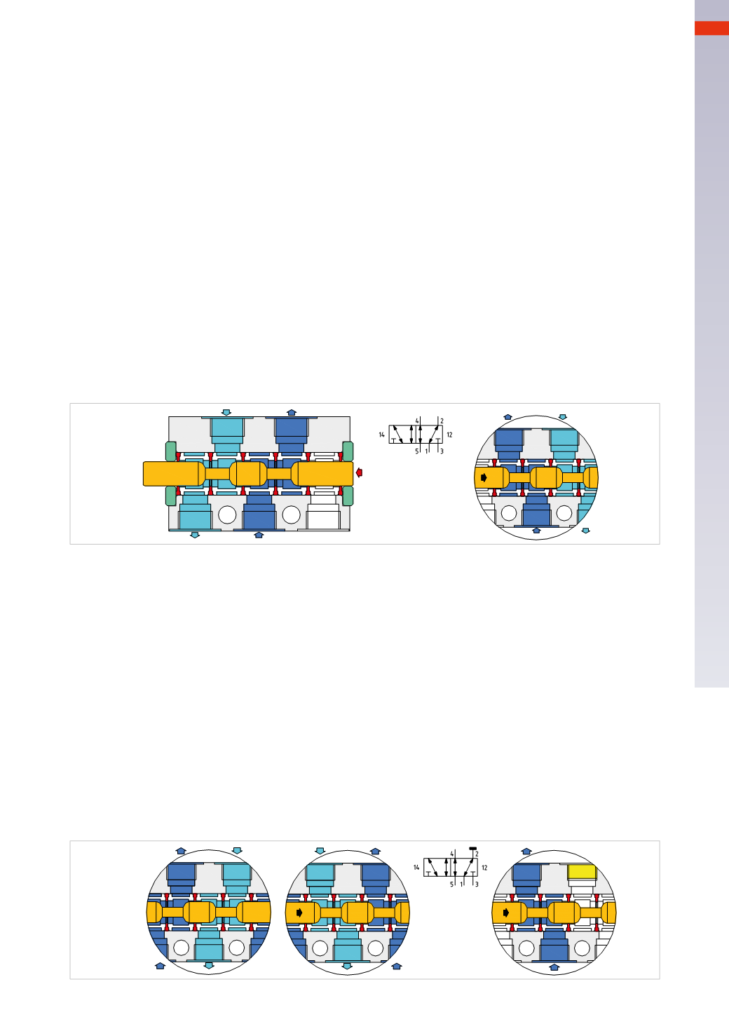
Fig. 17
5/2-way spool valves
In 3/2-way valves, compressed air is directed towards the only outlet, identified by the numerical value 2.
In the 5/2-way valves there are two outlets represented by the numbers, 2 and 4 respectively, with corresponding
exhaust ports 3 and 5.
• The supply pressure is always indicated by the number 1
• The outlet is indicated by the number 2 and its exhaust by the number 3
• The outlet is indicated by the number 4 and its exhaust by the number 5.
There are 5 ways while the positions are still 2. Having a greater number of passages, the spool has a different
structure with a greater amount of spacers and seals, and is consequently larger (longer) than a 3/2-way valve.
In5/2-way valves,NCorNO versions donot exist because the inlet 1 is always connected toone of the twooutlets
2 or 4.
Figure 17
Pos. A
:
the spool ismoved fully to the left as a result of the pilot signal 12,
inlet 1 is connected to outlet 2,
while exhaust port 3 is closed,
outlet 4 is connected to exhaust 5.
Pos. B
:
the spool hasmoved completely to the right as a result of the pilot signal 14,
inlet 1 is connected to outlet 4,
while exhaust 5 is closed,
outlet 2 is connectedwith exhaust 3.
As previouslymentioned, spool valves also allow for the use of different connections to the compressed air inlet.
Operation of the 5/2-way valvewith different supply pressure from exhausts ports 3 and 5.
Figure 18
Pos. C
:
the spool ismoved completely to the left as a result of the pilot signal 12,
the supply pressure from5 is in connectionwith outlet 4,
while 2 is exhausted through port 1,
the outlet pressure supply on port 3 is closed.
Pos. D
:
the spool hasmoved completely to the right as a result of the pilot signal 14,
the supply pressure from3 is in connectionwith outlet 2,
while 4 is exhausted through port 1,
the outlet pressure supply from port 5 is closed.
Use of a 5/2-way valve as a 3/2-way valve.
Pos. E
: to obtain this function, you only need to close one of the two outlets 2 or 4with a plug, the corresponding
exhaust may remain unused. The connection which is not used is indicated symbolically by a horizontal line.
The 5/2 valve is normally used to control a double acting cylinder, where themovement of the piston is obtained
by alternately introducing compressed air in a chamber while exhausting the opposite chamber.
3
1
5
4
2
3
1
5
4
2
3
1
5
4
2
Fig. 18
4
99
CAMOZZI
>
VALVES