


 104 / 218

Directly operated solenoid valves
In addition to the systems discussed above, the valves can also be charged over electrical signals, however, these
electrical signals must be converted into a pneumatic pilot signal. This operation is performed by the
solenoid
pilot valve
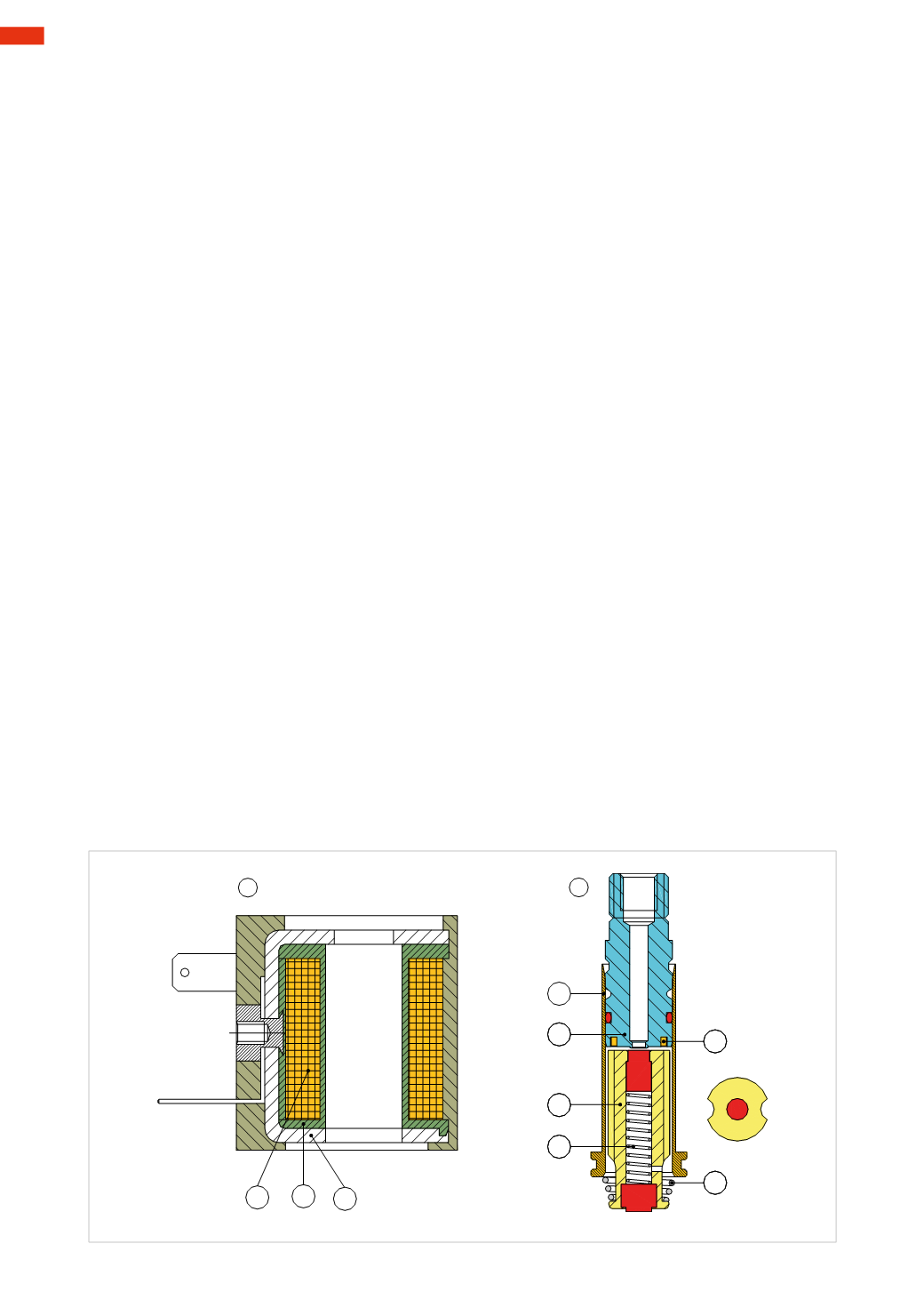
, which consists of the solenoid, electronics andmechanical components, a fixed plunger and themobile
plunger.
Figure 22
Pos. 1
:
the solenoid (coil)
The solenoid is formed by a winding of copper wire
A
, around a bobbin
B
protected by a metallic armature
C
.
It is often encapsulated in an isolating material which defines the shape and external dimensions. Electrical
connection is provided by two or three pins protruding from the solenoid. The arrangement of these pins determines
the shape and adheres to various standards such asDIN43650 andDIN40050. The solenoid, being an electrical
component, must be used in accordancewith certain criteria, themain being:
Temperature
: being a parameter that can vary considerably depending on where the solenoid is operating,
manufacturers will specify theminimum andmaximum compatible temperatures.
Humidity
: depending on the characteristics of the material used for over-molding, the solenoids can be suitable
for different applications.
Value of the current
: this depends on the electric power of the solenoid. Themodern solenoids generally need low
power in order to reduce consumption, heating and size.When operatingwithdirect current (DC), they require the
same current during the acceleration phase as well as during the holding phase.While operating with alternating
current (AC), they require a higher current value during the acceleration phase than during the holding phase.
Providing an alternating current to the solenoid without the internal mechanical part inside can cause damage.
It is important to disconnect the power supply or remove the connector from the solenoid before removing the
solenoid from the valve.
Duration of the electrical signal
: the solenoids are designed to provide the same performance level with constant
supply of electricity; this indication is normally identifiedwithED100%. In recent years different techniques, such
as the PWM (PulseWidthModulation) technology have becomewidespread.
Working environment
: all solenoids produce heat when supplied with an electric current. Installation in closed
control panels is tobe avoidedwhendeprived of adequate ventilation, or inhot environmentswith inadequateheat
dissipation, especially for groups of valves where the solenoids aremountedwithin close proximity.
Pos. 2
:
Fixed plunger andmobile plunger
The fixed plunger
E
is rigidlymounted on the plunger tube
D
, madewith non-magneticmaterial, stainless steel or
brass. The solenoid is fitted on the plunger tube.
The fixed plunger
E
has several functions: it contains the copper ring
G
, called the “phase shifting ring”, which
serves to reduce the vibrations produced by the magnetic field when using a power supply with an alternating
current. The central part of the fixed plunger can have an air passagewhich can be sealed off, (however this topic
will be approached later). It also limits the stroke of themobile plunger and allows for the closing of the solenoid.
Themobile plunger
F
has several functions: by providing voltage to the solenoid, it generates themagnetic field,
which pulls themobile plunger upwards, elevating it to be in contact with the fixed plunger
E
. The red-colored seal
in the upper section closes the orifice of the fixed plunger. The cylindrical internal spring
I
exerts a thrust force on
this seal ensuring the closure of the orifice. The lower seal, by rising together with themobile plunger, determines
the opening or closing of the passage of compressed air (C/A), (this will also be analyzed later).
Removing the voltage, themagnetic field ceases, the spring
H
repositions themobile plunger. The two grooves on
themobile plunger enable the air to reach the exhaust channel of the fixed plunger.
A B C
D
E
F
I
G
H
1
2
Fig. 22
4
102
CAMOZZI
>
VALVES