


 106 / 218

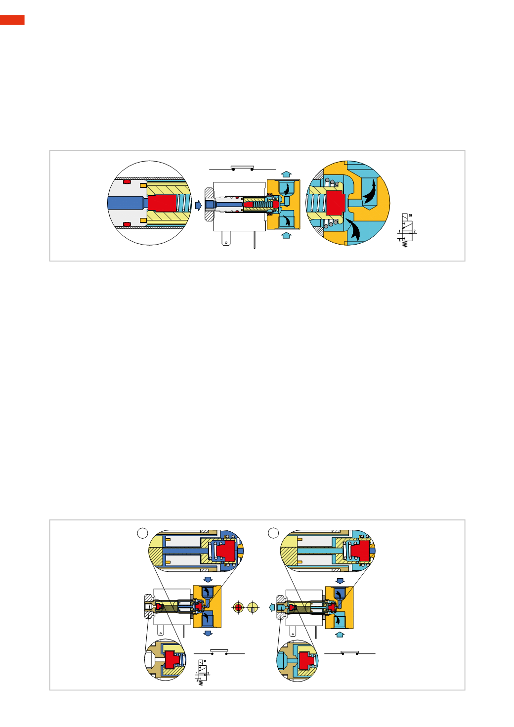
Figure 26
The electrical contact is closed, there is passage of electrical energy, and voltage is supplied to the solenoid.
Pos. C
: a current flows through the solenoid generating a magnetic field that pulls the mobile plunger upwards.
The conical spring compresses and the seal is detached from the orifice. It opens the passage of compressed air
from outlet 2 to exhaust 3.
Pos. D
: the surface of the upper part of themobile plunger is in contact with the lower surface of the fixed plunger,
the seal closes inlet 1 of the compressed air.
In this version the load of the conical spring is smaller than that of theNC solenoid valve, as itmust not overcome
the thrust of the C/Awhich attempts to raise themobile plunger. The reduced load of the conical spring offers a
smaller resistance to the lifting of themobile plunger triggered by themagnetic field.
C
D
3
2
1
Fig. 26
3/2-way NO solenoid valve
(3-way, 2-position, Normally Open, in-linemounting)
Inside the plunger tube constructionwe find three basic components:
• themobile plunger
• the fixed plunger
• the lower seal support.
Figure 27
Pos. 1
: rest position, open switch, absence of electrical energy.
A
: the spring, located outside the lower seal support, raises this support, enabling the air passage from inlet 1 to
outlet 2. This support has an extension in the shape of a rod, drilled in the central upper section, which through
the fixed plunger initiates contact with themobile plunger.
B
: themobile plunger, unaffected by themagnetic field, and due to the thrust of the lower seal support (described
above), is raised. The seal of themobile plunger that has been raised closes the orifice of the exhaust 3.
Pos. 2
: the electrical contact is closed and there is passage of electrical energy, and voltage is supplied to the
solenoid.
C
: the current flows through the solenoid generating a magnetic field, which depresses the mobile plunger and
consequently the lower seal support. This compresses the spring and the seal comes into contact with the lower
orifice, closing the inlet 1.
D
: themobile plunger is lowered by the effect of themagnetic field, and in addition to allowing the closure of inlet 1,
it detaches the upper seal from the exhaust orifice allowing the passage from the outlet 2 to the exhaust 3.
E
: section of the mobile plunger with the highlighted (red) upper seal and the milled groove, which allows the
passage of the compressed air.
The pneumatic symbol is completedwith a small square, which represents electrical pilot signal 10.
The command “10” indicates that in the presence of this signal, inlet 1 is closed.
2
2
1
3
3
A
1
B
E
C
D
1
2
Fig. 27
4
104
CAMOZZI
>
VALVES