


 112 / 218

Three-position valves
In these electrically or pneumatically operated valves, the third position is obtained through a repositioning spring
which ensures the return of the spool to the center position in the absence of a pilot signal. Themanually operated
valves offer two distinct solutions:
•
Monostable valve
: releasing the control lever in either direction, the spool is repositioned to the center due to
the action of the spring;
•
Bistable valve
: all positions are stable, in this case the central condition is obtainedmanuallybyactingon the lever.
The repositioning devicemay be realized in different ways, with separate springs in the two end caps or all on the
same side. The third position of these valves can possess different versions:
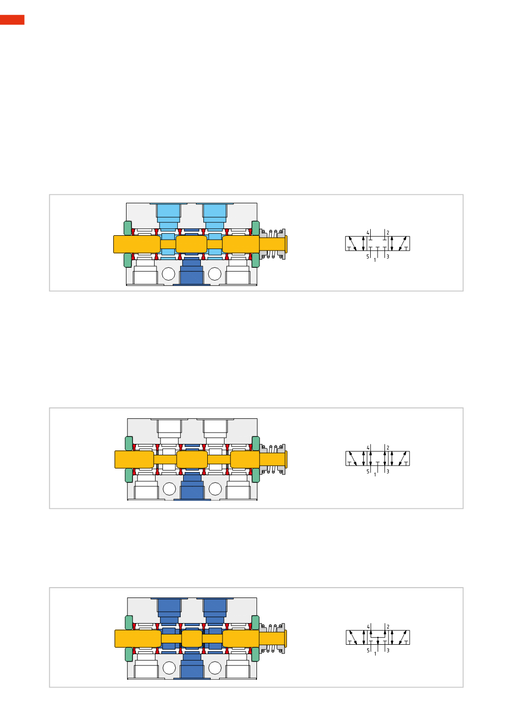
Figure 40
5/3CC - Closed centers
: inlet 1 closed, outlets 2 and 4 are closed, and exhaust 3 and 5 are also closed.
The central position (third position) ensures that all connections are closed, preventing air discharge and supply
to the cylinder. This type of valve is used to allow intermediate positions in cylinders. Not to be considered as a
safety- or precision component.
1
3
5
2
4
Fig. 40
Figure 41
5/3OC - Open centers
: inlet 1 is closed, outlets 2 and 4 are in communicationwith the exhaust ports 3 and 5.
The central position (third position) ensures that input 1 is closedwhile outlets 2 and4 are in connectionwith their
respective exhausts 3 and 5; this allows the exhaust of the cylinder chambers. This type of valve is usedwhen it is
necessary tomove thecylinder externally/from theoutsideonce it has stopped.With this typeof valve, as thecylinder
is in “neutral”, itwouldbepossible tomanuallymove thepiston rodbackand forth, likewiseany incorrectly positioned
external object would also cause it tomove. During the start-up phase, while feeding inlet 1with compressed air,
the cylinder will adopt an uncontrolled speed as the inner cylinder chambers are at atmospheric pressure.
In order to avoid damage fromuncontrolledmovements, there should be a gradual insertion of pressure during the
start-up phase.
1
3
5
2
4
Fig. 41
Figure 42
5/3 PC - Pressure Centers
: inlet 1 is in communication with outlets 2 and 4, exhaust ports 3 and 5 are closed.
The center position (third position) ensures inlet 1 is connected to both outlets 2 and 4while the exhausts 3 and
5 are closed; this allows the pressurization of both chambers of the cylinder. In this position there is a thrust force
acting on the piston in the positive direction, caused by the difference in the piston surfaces (areas) due to the
presence of the rod on the front side of the cylinder.
1
3
5
2
4
Fig. 42
4
110
CAMOZZI
>
VALVES