


 115 / 218

VALVES
1
1
2
2
12
12
REST
ACTUATED
A
B
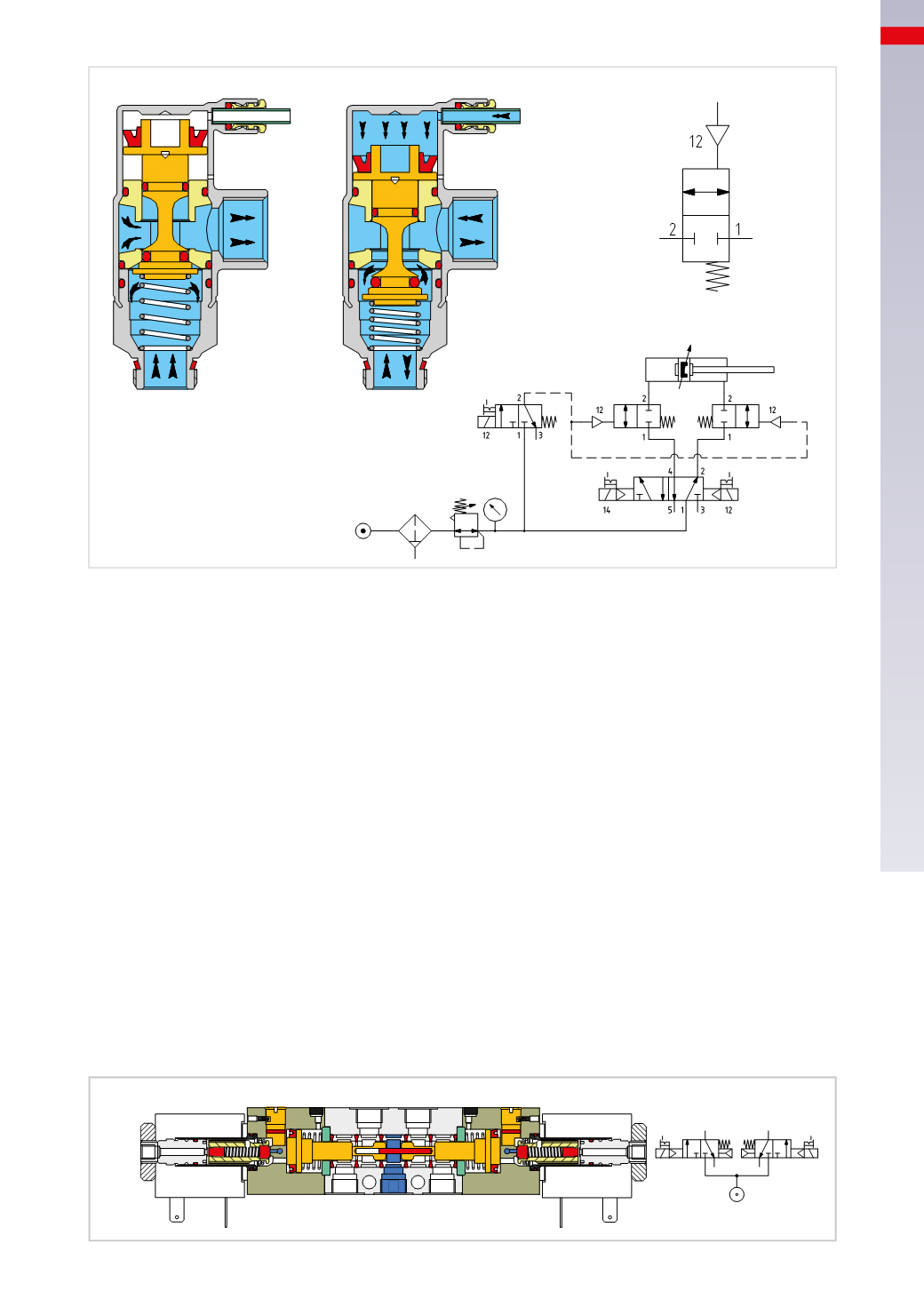
Fig. 45
Double 2/2-way and 3/2-way valves
Optimising space is often an important aspect for machine designers and as a consequence, reducing the overall
dimensions for each function is an important parameter for the valve manufacturer to consider. To optimize the
dimensions of valve blocks/valve islands, it is possible to integrate two 2/2-way or 3/2-way spools in one valve
body. In this way the overall dimensions are not those of two individual valves side by side, but those of a bistable
valve. Each 2 x 3/2-way or 2 x 2/2-way can comprise:
• two NC valves
• two NO valves
• one NO valve and one NC valve
Each valve, which is a part of the double 2/2-way or 3/2-way valve, is independent from the other and has its own
pilot signal, which can be pneumatic or electric.
Figure 46
2 x 3/2-way NC valve electrically operated
In the body of the double valve there are two spools with a 3/2-way NC function with return springs and two
sets of electric pilot signals. In the absence of pilot signals 12 and 14 (rest position) the channels from inlet 1
to outlets 2 and 4 are closed. With the pilot signal 12, the spool on the right side moves to the left, opening the
passage of compressed air from inlet 1 to outlet 2, when the pilot signal is interrupted, the spring repositions the
spool closing inlet 1, and connects outlet 2 to exhaust 3. With pilot signal 14, the spool on the left side moves to
the right, opening the passage of compressed air from inlet 1 to outlet 4, when the pilot signal is interrupted, the
spring repositions the spool closing inlet 1 and connects outlet 4 with exhaust 5. With the two pilot signals 12 and
14 activated simultaneously, the passages from inlet 1 to outlets 2 and 4 are open; in this case the airflow rate is
reduced, as both outlets are open simultaneously.
1
4
5
3 1
2
14
12
14
12
1
5
3
2
4
Fig. 46
4
113
CAMOZZI
>
VALVES