


 117 / 218

VALVES
Signal processing valves
“Logic valves” or “logic functions” are pneumatic valves with reduced dimensions and flow rates, normally,
low-pressure signals are sufficient for piloting. They are particularly suitable for processing signals in order to
achieve awork sequence. These valves are generally poppet valves with the following functions:
NOT
: corresponds to the operation of a monostable 3/2-way, NO valve, pneumatically operated and mechanical
spring return.
YES
: corresponds to the operation of a monostable 3/2-way NC valve, pneumatically operated and mechanical
spring return.
AND
: as by definition, this logic valve requires two continuous incoming signals to generate an output, and not
necessarily simultaneously. This is sometimes called a “Select valve”.
OR
: as by definition, this logic valve requires at least one of the two input signals to generate an output signal.
Memory
: corresponds to a bistable 5/2-way valve pneumatically operated.
Signal amplifier
: in the presence of a low-pressure pilot there is a high-pressure output.
Pneumatic sensors of the sender receiver type
(interruption of air stream): are an alternative to mechanically
operated sensors, a mechanical contact is not necessary, it is sufficient for an object in their field of action to
generate an output signal.
Logic functionNOT
The logic NOT function is a
3/2-way NO
monostable pneumatically operated valve. The difference between a
normal 3/2-way valve and a NOT function is that the latter requires a very low-pressure value for the pilot signal
(0,3
bar
).
One of the most common uses of this function is to signal the end position of a cylinder. During movement, the
value of the pressure in the exhaust chamber remains at a constant value and then decreases to the vicinity of the
limit switch. This value is sufficient to operate the NOT switch which only activates when the piston rod/piston
ceases itsmovement, i.e. with atmospheric pressure in the chamber.
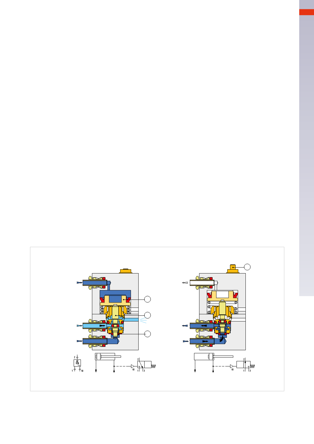
Figure 49
Pos. A
:
in the presence of the pilot signal, inlet 1 is closed and outlet 2 is in communication with exhaust 3.
Thepiston rod/piston isat thenegativeendposition thenegativechamber ispressurizedand theNOT isactivated, (10).
In the presence of the pilot signal, the piston
C
pushes down the
D
. The spring compresses and the
D
, through the
seal
E
closes the passage of compressed air from inlet 1 to outlet 2, the passage from outlet 2 to exhaust 3 opens.
Pos. B
:
in the absence of a pilot signal, inlet 1 is open towards the outlet 2.
The piston rod/piston is at the positive end position and the negative chamber is at atmospheric pressure, theNOT
is not activated, (10). In the absence of the pilot signal, the spring that was compressed extends and lifts
D
and
piston
C
. It opens the passage through the seal
E
; input 1 is now in connection with outlet 2. The presence of
pressure in outlet 2 is indicated by the extended indicator
F
.
A
B
1
2
1
2
3
3
C
D
E
F
10
10
Fig. 49
When flow regulators areused for speed control, it is necessary to connect theNOTbetween the flow regulator and
the cylinder. Unlike the sensors withmechanical control, these valves do not read the actual stroke end position,
but respond to the presence of air inside the chambers. In the case of an eventual external blocking whichwould
prevent the full stroke of the piston rod/piston, theNOT valve gives the output signal.
4
115
CAMOZZI
>
VALVES