


 118 / 218

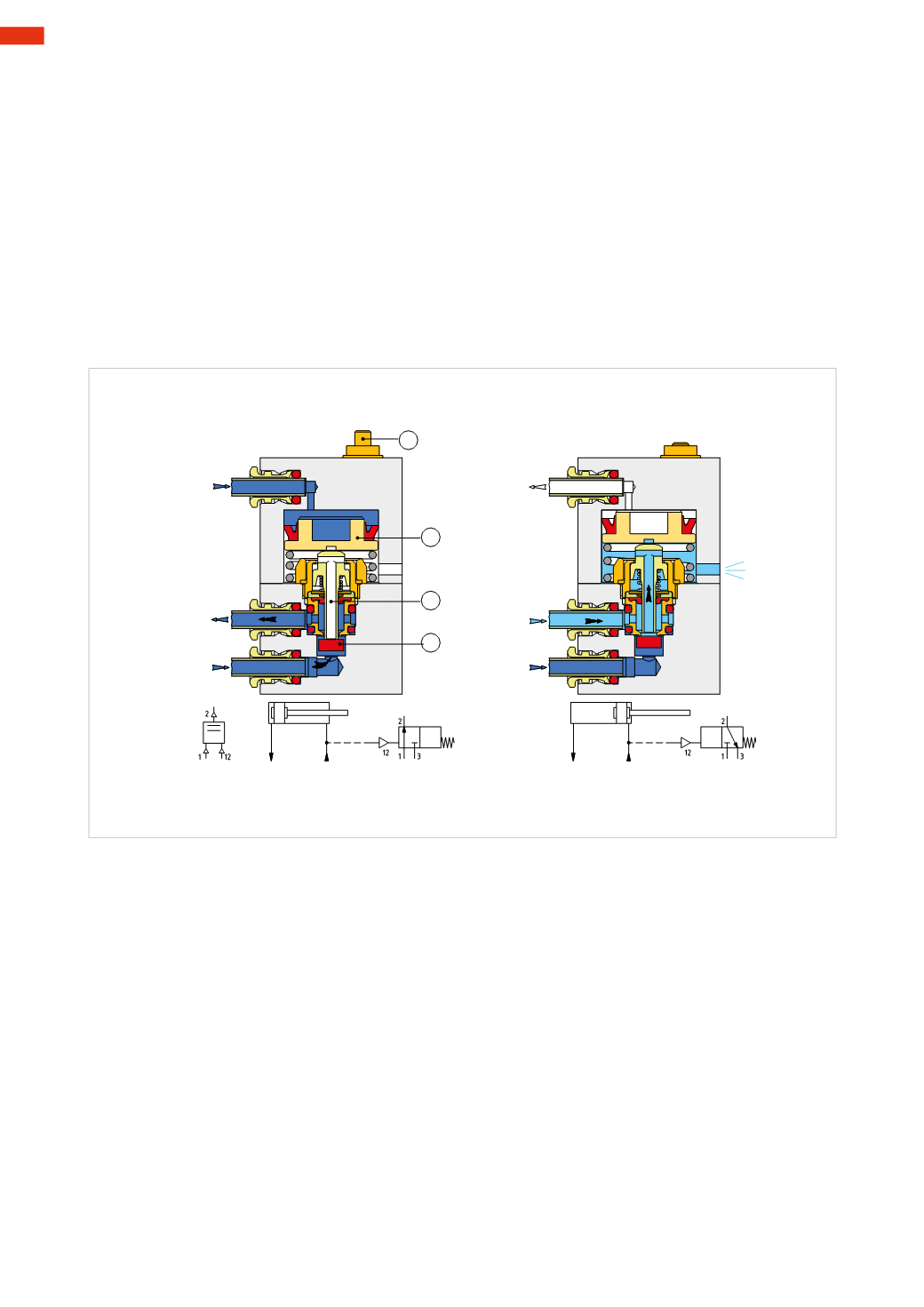
Logic function YES
The logic valve YES is a 3/2-way NCmonostable pneumatically operated valve.
As in the previous situation, a very low-pressure value for the pilot signal (0.3
bar
) is required.
Used less frequently than theNOT function, it finds applications in pneumatic logic circuits.
Figure 50
Pos. A
:
in the presence of a pilot signal, inlet 1 is open towards outlet 2.
The cylinder is at the negative end stroke position, and the negative chamber is pressurized, the pilot signal is
under pressure (12). In the presence of the pilot signal, piston
C
pushes down the hollow stem
D
. The spring is
compressed, and the hollow stem, through the seal
E
, opens the passage of C/A from inlet 1 to outlet 2. The seal
E
keeps thepassage
D
of the stem closed. Thepresenceof pressure inoutlet 2 is indicatedby theextended indicator
F
.
Pos. B
:
in the absence of a pilot signal, inlet 1 is closed and outlet 2 is in connectionwith exhaust 3.
The cylinder is at the positive end stroke position. The negative chamber is at atmospheric pressure, and there is
no pilot signal (12). In the absence of a pilot signal, the spring, whichwas formerly compressed, is extended and
lifts the hollow stem
D
and the piston
C
. The seal
E
is detached from the hollow stem closing inlet 1 and opening
passage
D
on the hollow stem. Outlet 2 is in connectionwith exhaust 3.
A
B
1
2
1
2
3
3
C
D
E
F
12
12
Fig. 50
In the situation whereby flow regulators are used for speed control, it is necessary to connect the YES between
the flow regulator and the cylinder.
Logic functions OR and AND
The logic functions AND andOR are used in the design of pneumatic circuits, where certain conditions are required
to allow the passage of pneumatic signals.
Logic functionOR
This is a logic valve that has the function of a circuit selector.
It has three pneumatic connections: two inlets and one outlet.
To generate a signal at the outlet, the continuous presence of pressure in at least one of the two inlets is required.
Figure 51
Pos. 1
:
presence of inlet
P
on the upper side only. The incoming C/A pushes the seal
G
against the orifice located
on the insert, the passage to the lower inlet
P
is closed. The passage to the outlet
A
is opened.
The presence of outlet
A
is indicated by the extended indicator
B
.
Pos. 2
:
presence of signal on the inlet
P
on the lower side only. The incoming C/A raises the seal
G
against the
upper orifice of the valve body, the passage to the upper inlet
P
is closed. The passage to the outlet
A
is opened.
The presence of pressure in outlet
A
is indicated by the extended indicator
B
.
Pos. 3
:
absence of input signals. In the absence of pneumatic inputs there is no output. If there are two
P
inlets
simultaneously, the first signal at outlet
A
is the fastestwhen the pressure is equal, however with differing pressures
the first signal is always the onewith the higher pressure. The indicator
B
due to the spring is in rest position.
4
116
CAMOZZI
>
VALVES