


 129 / 218

VALVES
Part 2
Themost commonly used flow regulation valves areunidirectional valves, in this sectionwe offer a further analysis
of their features.
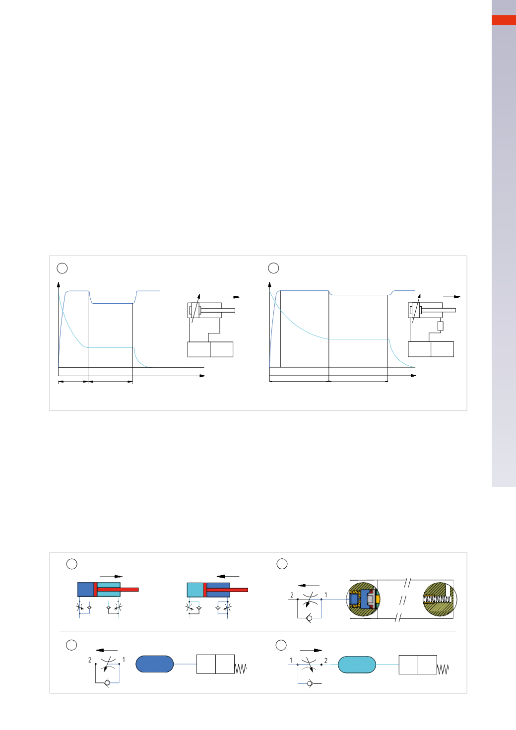
Figure 63
Pos. 1
:
the graph represents the time and pressure in the two chambers of the cylinder during the positive and
negative strokes and in the absence of the flow regulator. The distance
t
1
on the time axis represents the time
between the activation of the solenoid valve, the beginning of the pressurization of the positive chamber and the
exhaust of the negative chamber.
The distanc
t
2
represents the time of the stroke from the start of the exhaust of the negative chamber until the
beginning of the cushioning phase of the piston against the end cap. By activating the solenoid valve, the pressure
in the positive chamber increases, while the pressure in the negative chamber decreases. There is nomovement
since the pressure has not yet reached a value such as to generate a force capable of overcoming the load and the
resistance of the exhausting air. (time
t
1
)
As soon as themovement of the piston starts the volume of the positive chamber increases, the pressure is slightly
reduced then stabilizes since the flow rate of the valve is adapted to this constant volume change. (time
t
2
)
The piston comes in contact with the cushion seal of the cylinder, the variation in volume is now smaller and
therefore the pressure tends to rise again. The piston stops at the end cap, the pressure stabilizes.
Pos. 2
:
in this case a flow regulator ismounted on the negative chamber, the times
t
1
and
t
2
increase.
The pressure in the negative chamber is not dischargedwith the same speed as shown inPos.
1
as the flow regulator
has a reduced passage. Pressure is created in the negative chamber, which opposes the thrust of the piston,
therefore the speed decreases.
Time
Time
Pressure
Pressure
t
1
t
2
t
1
t
2
1
2
Fig. 63
Figure 64
Pos. 1
: we have a double acting cylinder with adjustable speed in both directions. In the positive stroke the flow
freely crosses the undirectional valve inside the regulator providing the highest flow rate. In the negative chamber
the unidirectional valve forces the flow to pass through the adjustment screw.
Pos. 2
:
flow regulators can also be used for other functions, for example the return of a pneumatically operated
valve can be delayed. The valve is activated immediatelywith the arrival of the pneumatic pilot signal, during the
return phase (when the pilot signal disappears), the reduced cross section delays the exhaust,maintaining pressure
on the pilot piston for a slightly longer duration.
Pos. 3
:
the volume/capacity positioned between the flow regulator and the pilot signal of the valve allows for this
delay to be increased.
Pos. 4
: mounting the flow regulator in the opposite way results in a delay in the piloting phase of the valve, the
return is fast as the flow is free to exhaust.
1
2
3
4
Fig. 64
4
127
CAMOZZI
>
VALVES