


 125 / 218

VALVES
meters
Nl/min.
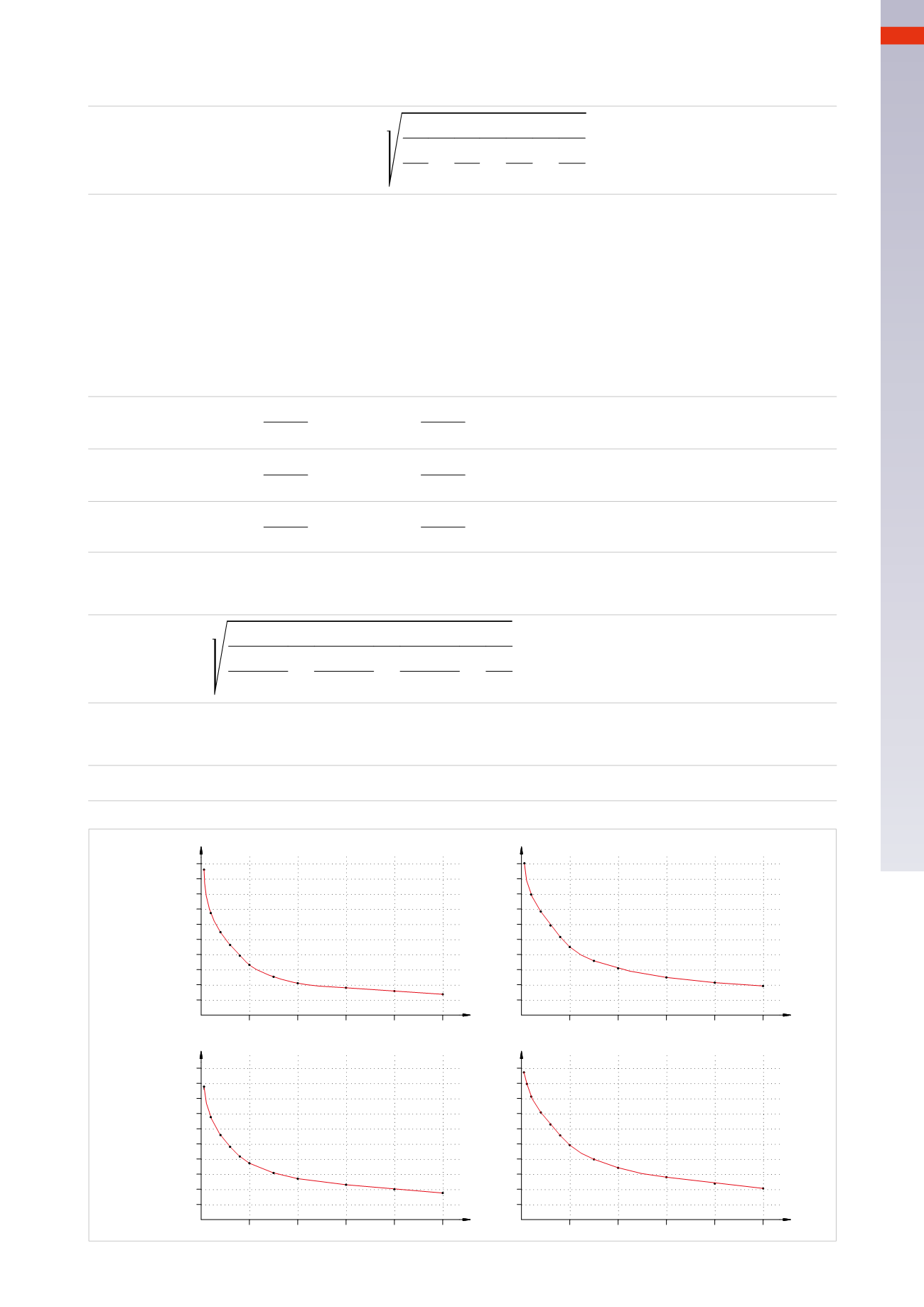
NOMINALFLOWOFTUBES4/2
meters
Nl/min.
NOMINALFLOWOFTUBES 6/4
5
10
15
20
25
0
meters
Nl/min.
NOMINALFLOWOFTUBES8/6
1400
700
280
140
420
560
980
840
1120
1260
5
10
15
20
25
0
5
10
15
20
25
0
50
150
100
200
300
250
350
450
400
500
25
50
75
100
125
5
10
15
20
25
0
meters
Nl/min.
NOMINALFLOWOFTUBES10/8
2200
1980
1760
1540
1320
1100
880
660
440
220
Fig. 58
The value assumed by conductance of many elements in series is defined by the formula:
1
C
=
1
+
1
+
1
+
1
C C C C
1
3
2
3
3
3
n
3
3
Where
C
is the conductance of each element considered singularly.
We insert the data (calculated or obtained from the graph of the tube flow) into the formula. (
Fig. 58
).
Q
n
1
=320
Nl
/
min
tube diameter 6/4
L
= 2,5
m
. from the air treatment to the valve
Q
n
2
=400
Nl
/
min
valve
Q
n
3
=320
Nl
/
min
tube diameter 6/4
L
= 2,5
m
. valve-to-cylinder
The respective values of conductance are:
C
1
=
Q
n
1
C
1
=
320
C
1
=
69,56
Nl / min * bar
X
4,6
C
2
=
Q
n
2
C
2
=
400
C
2
=
86,95
Nl / min * bar
X
4,6
C
3
=
Q
n
3
C
3
=
320
C
3
=
69,56
Nl / min * bar
X
4,6
By entering values into the formula you obtain the value of the total conductance:
1
C
tot
=
1
+
1
+
1
69,56
3
86,95
3
69,56
3
3
C
tot
=
51,18
Nl / min * bar
Fromwhich:
Q
n
=
C
*
4,6
Q
n
= 51,18
*
4,6
Q
n
=
235
Nl / min
4
123
CAMOZZI
>
VALVES