


 128 / 218

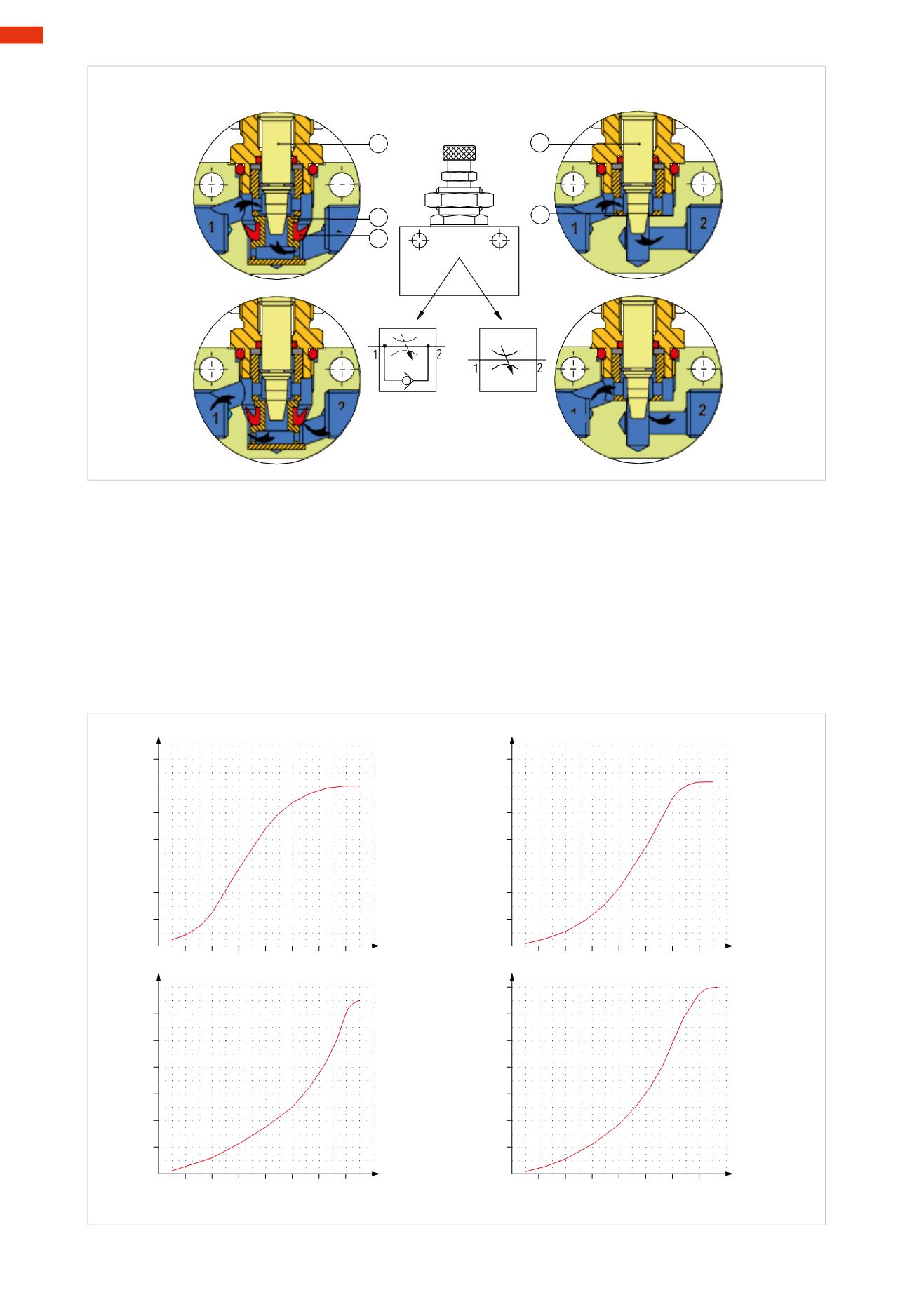
Unidirectional
Bidirectional
A
C
B
D
A
A
B
C
D
1
2
1
2
1
2
1
2
Fig. 61
Figure 62
To select the correct dimensions of the flow regulator, it is advisable to consider the following:
• The value of themaximum flow ratewith the adjusting screw fully open.
•The flow rate in the non adjustable direction: a certain amount of compressed airmust reach the thrust chamber
of the cylinder to ensure constant pressure. During the movement of the cylinder, the volume of the thrust
chamber continually changes and the amount of compressed air enteringmust always be able to compensate
for this volume change, otherwise themovement would be erratic.
• The gradient of the curve indicates the flow rate based on the number of turns of the adjusting screw:
the volume of compressed air within the chambers of the cylinder depends on the diameter, the stroke and the
supplied pressure. Referring to graphs illustrating the flow characteristics, allows for the selection of the most
appropriate flow regulator that enables themost optimal and precise adjustment..
0 2 4 6 8 10 12 14
200
400
600
800
1000
1200
0 2 4 6 8 10 12 14
20
40
60
80
100
120
1400
0 2 4 6 8 10 12 14
100
200
300
400
500
600
0 2 4 6 8 10 12 14
65
130
195
260
325
390
455
140
N° turns
adjusting screw
N° turns
adjusting screw
N° turns
adjusting screw
N° turns
adjusting screw
Qn
Nl/min.
Qn
Nl/min.
Ø 4mm
Ø 6mm
Ø 8mm
Ø 10mm
800
Fig. 62
4
126
CAMOZZI
>
VALVES