


 126 / 218

Final conclusions
:
The cylinder in question, with a diameter of 50
mm
, stroke length 250
mm
, to complete the stroke in a
time of 1,5
sec
. requires at least 137
Nl
/
min
. Assuming we use a valve with a flow rate of
Q
n
= 400
Nl
/
min
and various connecting tubes with a 6/4 diameter with total length of 5
mt
. the nominal flow rate of the system
becomes:
Q
n
=
235
Nl
/
min
This flow rate is greater than required, and therefore fulfils the request; also, the pressure drop of the system is less
than 1
bar
and therefore has a large safetymargin.
Interception valves
Non-return or unidirectional valves.
These valves block the passage of compressedair inanyundesireddirection. As a consequence of the phenomenon
of expansion of gases, the direction of flow always points towards the chamber with the lower pressure. If the C/A
contained in two connected containers (regardless of their volume or distance) is not intercepted, the compressed
air disperses and balances the pressure.
Normally the distribution of compressed air includes an initial receiver (accumulator tank) locatedupstream of the
distributionnetwork. The pneumatic devices connected to the network can include additional small compensation
tanks. For the phenomenon described above, if the pressure in the initial accumulator tank should decrease, there
wouldbe anundesired transition of the compressedair, seeking to returnupstream from the compensation storage
tanks. To avoid this process, non-return or unidirectional valves are used.
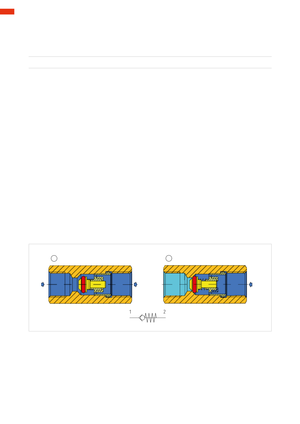
Figure 59
Pos. 1
:
the unidirectional valve comprises a body which houses a poppet with its own seal as well as a spring.
The compressed air that is only able to pass from left to rightmust have a pressure such as to overcome the spring
force and the downstream pressure.
Pos. 2
:
when the value of the downstream pressure combined with the thrust of the spring is higher than the
upstream pressure, the poppet moves to the left closing the passage.
1
2
1
2
1
2
Fig. 59
Quick exhaust valves.
This valve is mounted directly on the cylinder ports or a chamber, and diverts the flow of the C/A, exhausting
it directly into the atmosphere. This method stops the C/A in exhaust to return back through the tubing and the
control valve, allowing a reduced exhaust time and consequently accelerating themovement of the cylinder.
The absence of an internal spring allows the quick exhaust valve to switch evenwith very low pressure.
Figure 60
Pos.1
:
thebodyof thequickexhaust valveconsistsof twoparts screwed together, insidewhicha lip seal ispositioned.
The C/A arriving from inlet 1moves the seal towards the right, closing the passage to exhaust 3 and opening the
passage towards outlet 2 connected to the cylinder chamber.
Pos. 2
:
when the C/A of the cylinder is to be exhausted as there is no more pressure at inlet 1, it passes back
through outlet 2, moves the seal which closes inlet 1 and opens exhaust 3.
4
124
CAMOZZI
>
VALVES