


 130 / 218

Part 3
These valves enable the “control” of the speed of the piston rod/pistonmovement in the pneumatic cylinders, by
the nears of themanual flow regulation device.
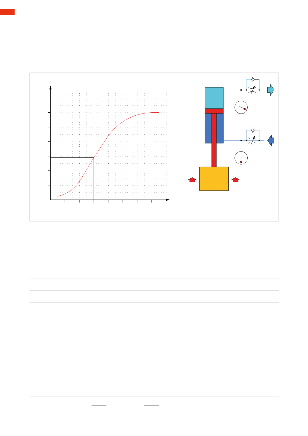
Figure 65
The information provided in this chapter serves to assist in selecting the size of the flow control valve and therefore
calculate theperformanceof thecylinder connected to thisdevice.Please refer to thegraphs included in thecatalogues
that illustrate the nominal flow rate in relation to the number of turns of the adjusting screw.
0 2 4 6 8 10 12 14
20
40
60
80
100
120
140
N° turns
adjusting screw
Qn
Nl/min.
Fig. 65
Example:
we have a cylinder of diameter 63
mm
; stroke length400
mm
, with the piston rod pointing downwards.
A load is applied on the piston rod. On the cylinder, two flow regulators are connected.
When lifting the load, the compressed air present in the positive chamber of the cylinder is exhausted, the value of
the load applied to the rod remains unchanged throughout the stroke. Let’s assume that during themovement the
pressure value in the exhausting chamber is 3
bar
and the flow regulator valve is open at 6 turns.
Calculation of the volume in the exhaust chamber
V
s
V
s
=
(
π
*
π
* 3,14)
*
Stroke
V
s
=
(31,5 * 31,5 * 3,14) * 400
V
s
=3115 * 400
V
s
=1.246.266
mm
3
V
s
≅
1,25
dm
3
Considering that the exhaust pressure
P
has a value of 3
bar
the volume
V
3
becomes:
V
3
=
V
s
* (
P
+ 1)
V
3
=1,25
*
(3+ 1)
V
3
=
5
Nl
This is the amount of air, which is exhausted into the atmosphere once it passes the flow regulator. The capacity
of the flow regulators is defined as nominal flow
Q
n
, calculatedwith 6
bar
at the inlet and
∆
p
=1.
As discussed in previous chapters, it is possible to calculate the flow of free air at a certain pressure given the
nominal flow rate
Q
n
.
This hypothetical regulator has a value
Q
n
of just under 60
Nl
/
min
. Using the formulas already knownwe obtain
the flow rate value at a pressure of 3
bar
.
Calculation of the conductance
C
:
C
=
Q
n
C
=
60
C
=
13
Nl / min * bar
4,6
4,6
4
128
CAMOZZI
>
VALVES