


 127 / 218

VALVES
Time
Time
Pressure
Pressure
t
1
t
2
t
1
t
2
1
2
2
3
1
3
1
2
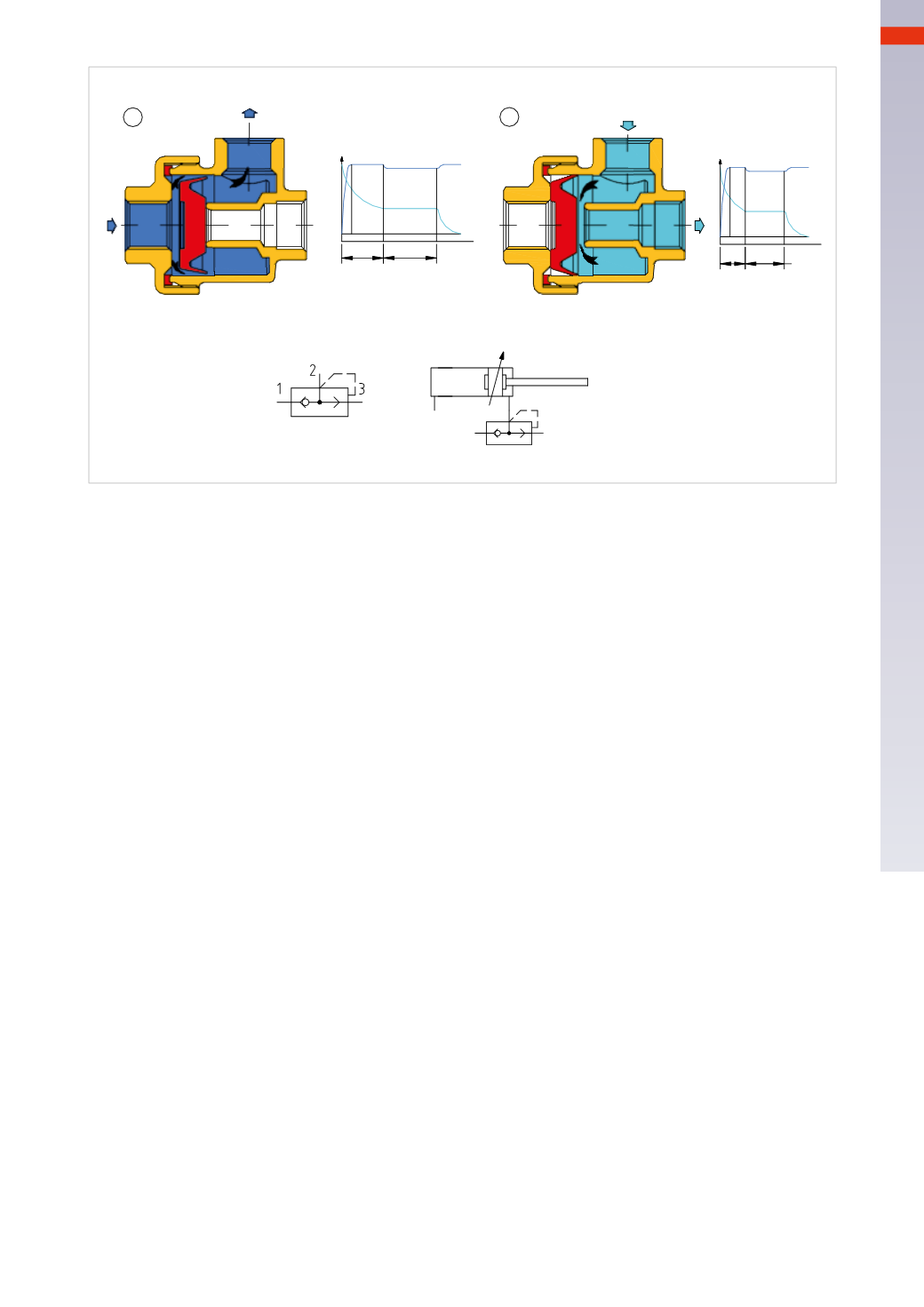
Fig. 60
Thediagrams show thedifferent behavior of theC/A in the two chambers of adoubleacting cylinder in thepresence
or absence of a quick exhaust valve.
The value
t
1
indicates the time that elapses between the change of the position of the valve (including the
pressurization time of the cylinder) and the beginning of the movement of the piston. Observe how the curves,
which represent the exhaust phase, vary in the two graphs. The value
t
2
indicates the duration time of the
piston stroke. This value is noticeably different in the two graphs because the pressure in the exhaust is released
immediately into the atmospherewithout it going back through the connecting tubes or the control valve.
Note
: it is not advisable to use quick exhaust valves combinedwith 5/3CC valves.
Flow control valves
Part 1
The flow control valves regulate the passage of compressed air through the variation of their internal cross section.
By regulating the flow, it is possible to adjust the speed of the pistons in pneumatic cylinders. The control should
always be performed on the exhausting chamber. Incoming air is only regulated on single acting cylinders.
Unidirectional flow regulator
The connection1 connects to the volume to be regulated and connection2 is the connection directed towards the
main directional valve.
Figure 61
Pos. A
:
the flow of compressed air exiting the chamber enters the regulator via connection 1. The compressed air
encounters lip seal
C
mounted on cartridge
B
and expands to contact with the body of the regulator, creating the
unidirectional function. The compressed air is therefore forced to pass through the reduced cross section created
by the conical part of the adjusting screw
A
and the orifice on the cartridge
B
.
Pos. B
:
the incoming flow of compressed air to the chamber enters the regulator via connection 2. The lip seal
C
gives way, opening the passage and allowing the transit of flow both inside and outside the cartridge
B
. In this
direction the flow is not regulated.
Bidirectional flow regulator
Pos. C
:
the flow of compressed air exiting the chamber enters the regulator via connection 1. In this situation
neither the cartridge
B
or its lip seal are included. The compressed air is forced to pass through the reduced cross
section created by the conical part of the adjustment screw
A
, which bymoving upwards or downwards, changes
the passage cross section between cone and the orifice
D
.
Pos. D
:
the incoming flow of compressed air through connection2 is forced to pass as in the previous case, through
the reduced cross section created by the conical part of the adjustment screw
A
, which through its upwards or
downwardsmovement, changes the passage cross section between the cone and the orifice
D
.
4
125
CAMOZZI
>
VALVES