


 136 / 218

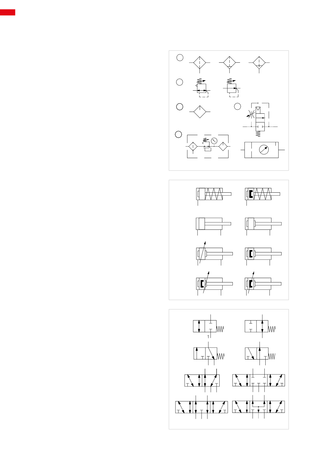
Figure 1
Air preparation
Pos. 1:
A
:
Filter
- generic representation
B
:
Filter
- with manual condensate drain
C
:
Filter
- with automatic condensate drain
Pos. 2:
A
:
Pressure regulator
- with relieving; with discharge
of the excess pressure, (relieving). The line with
two arrows indicates the direction of the main flow
towards the point of use, and the direction of discharge
of the excess pressure.
B
:
Pressure regulator
- without relieving; without
discharge of the excess pressure.
(Note: the small triangle on the upper left is omitted)
Pos. 3: Lubricator
- generic representation
Pos. 4: Soft start valve
- provides a gradual regulated
flow to the compressed air system.
Upon reaching approx. 50% of the inlet pressure, the
valve fully opens the passage. The arrow indicates
the direction of flow.
Pos. 5:
A
:
F.R.L
, group, detailed symbol
B
:
F.R.L
, group, simplified symbol
Figure 2
Cylinders
A
:
Single-acting cylinder - non magnetic
with mechanical
spring return, fixed mechanical cushioning, negative
stroke
B
:
Single-acting cylinder - magnetic
with mechanical
spring return, fixed mechanical cushioning, negative
stroke
C
:
Double-acting cylinder, non magnetic
D
:
Double-acting cylinder, non magnetic
with fixed
mechanical cushioning on both sides of the piston
E
:
Double-acting cylinder, non magnetic
with
adjustable pneumatic cushioning in both directions
F
:
Double-acting cylinder, magnetic
with fixed
mechanical cushioning in both directions
G
:
Double-acting cylinder, magnetic
with adjustable
pneumatic cushioning positive stroke and fixed
mechanical cushioning negative stroke
H
:
Double-acting cylinder, magnetic
with adjustable
pneumatic cushioning in both directions
Figure 3
Directional control valves
A
:
2/2-way monostable
closed in rest position
(2/2-way NC)
B
:
2/2-way monostable
open in rest position
(2/2-way NO)
C
:
3/2-way monostable
closed in rest position
(3/2-way NC)
D
:
3/2-way monostable
open in rest position
(3/2-way NO)
E
:
5/2-way
F
:
5/3-way
valves with closed centers (5/3-way CC)
G
:
5/3-way
with open centers (5/3-way CO)
H
:
5/3-way
with pressure centres (5/3-way CP)
Pneumatic symbols
The drawings demonstrating the construction and functional characteristics of the components described in the
previous chapter also illustrate the relevant symbols. The symbols are listed here alongside a brief description.
1
2
3
5
4
A
B
C
A
B
A
B
Fig. 1
A
B
C
D
E
F
G
H
Fig. 2
The direction of the arrow indicates the direction
of flow, some symbols must be completed with the
addition of an operation and return device.
A
C
E
G
B
D
F
H
Fig. 3
5
134
CAMOZZI
>
CIRCUIT TECHNIQUE